On the journey towards a programmable Christmas lights display using a modular ATTiny85 board I have designed, and with the success of the giant alphanumeric display showing I can control multiple outputs, it’s on to making those outputs a significantly different voltage. This requires an additional MOSFET component to do the switching allowing me to use common 12v lights. On to sourcing the parts.
The ingredients

The MOSFETs. These are being used in place of relays so that there will be no crazy clicking going on while the channels change. Relays could be substituted in if a true voltage divide is required.
More veroboard. Always running out of this and it’s quite costly. This project will use the best part of a sheet.

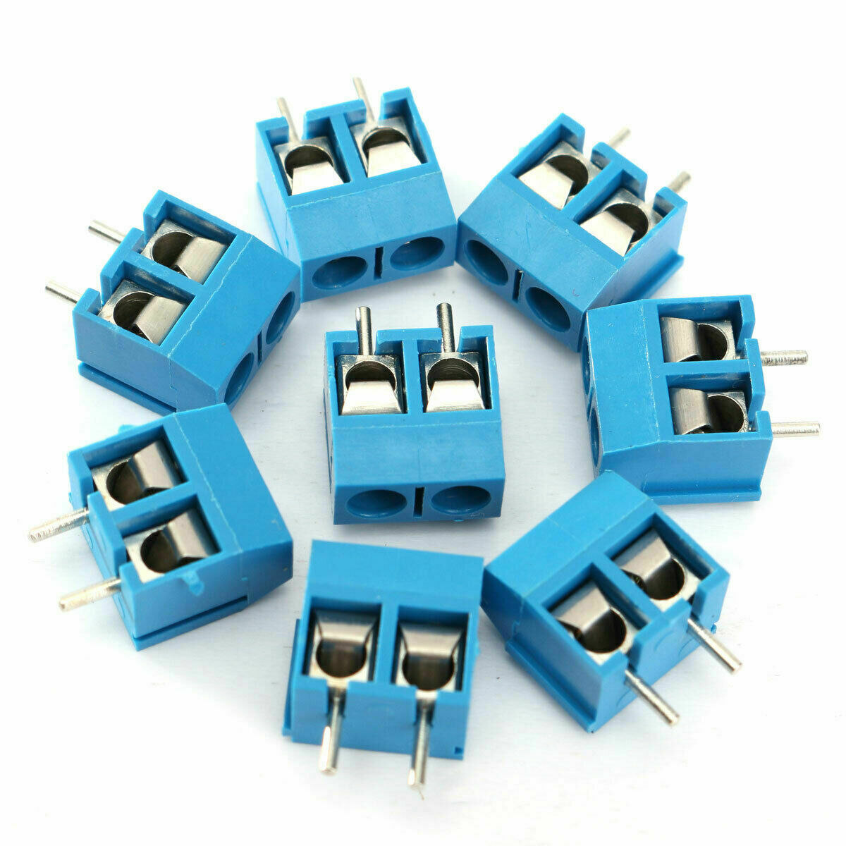
I have gone with screw terminals for the higher voltage wires as they will be thicker and it will allow me to swap them around much quicker.
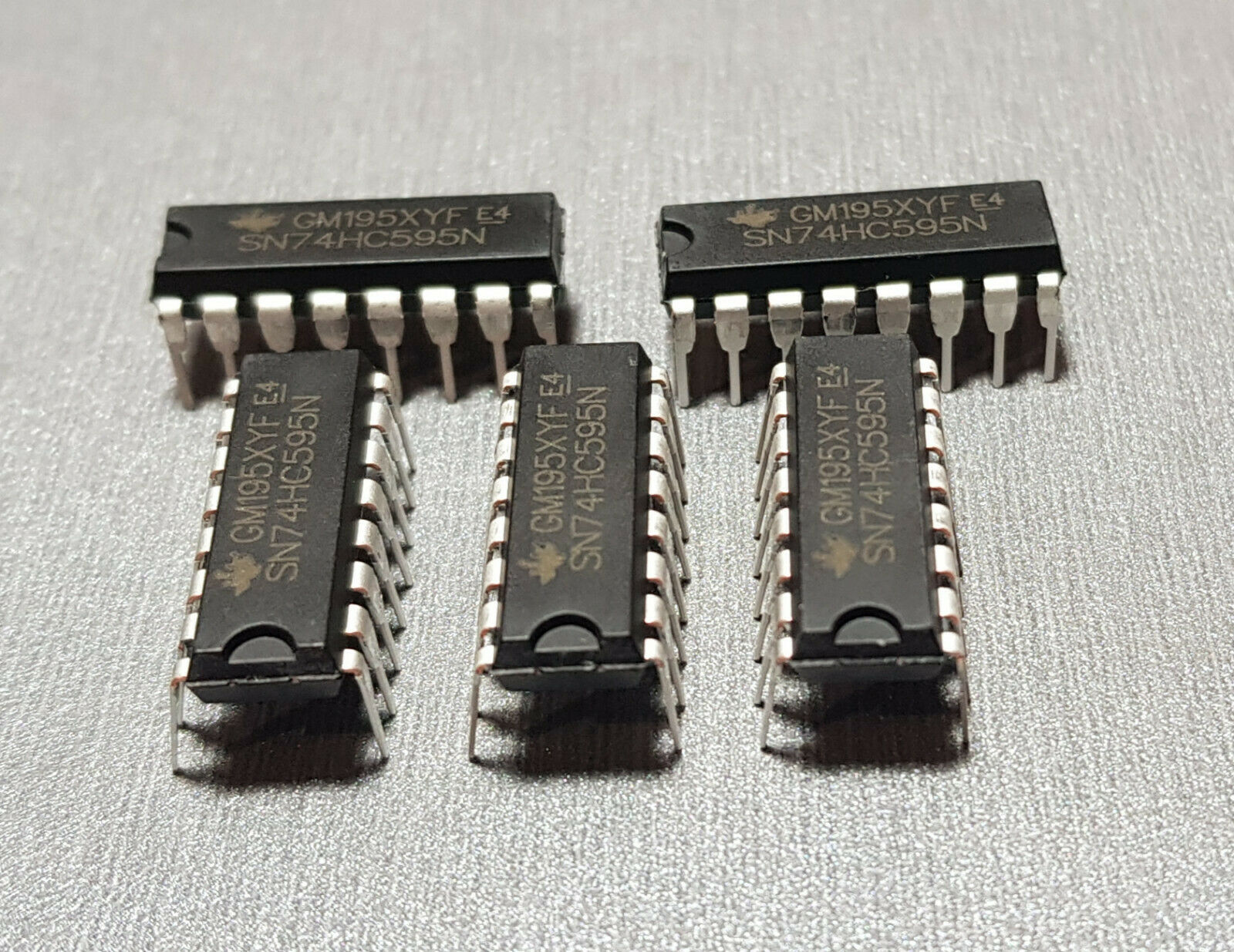
The common shift register 74hc595 as used in previous projects and available fairly cheap. I had some left over from past projects but this will be using two of them, and a clone of the double shift board used in the giant alphanumeric display project.
On to the hero of the project – the leds. These are 12v and quite bright. This is why the MOSFETs are required as the arduino can’t power these alone. The idea being if I can power these on and off rapidly, then the next project can commence!

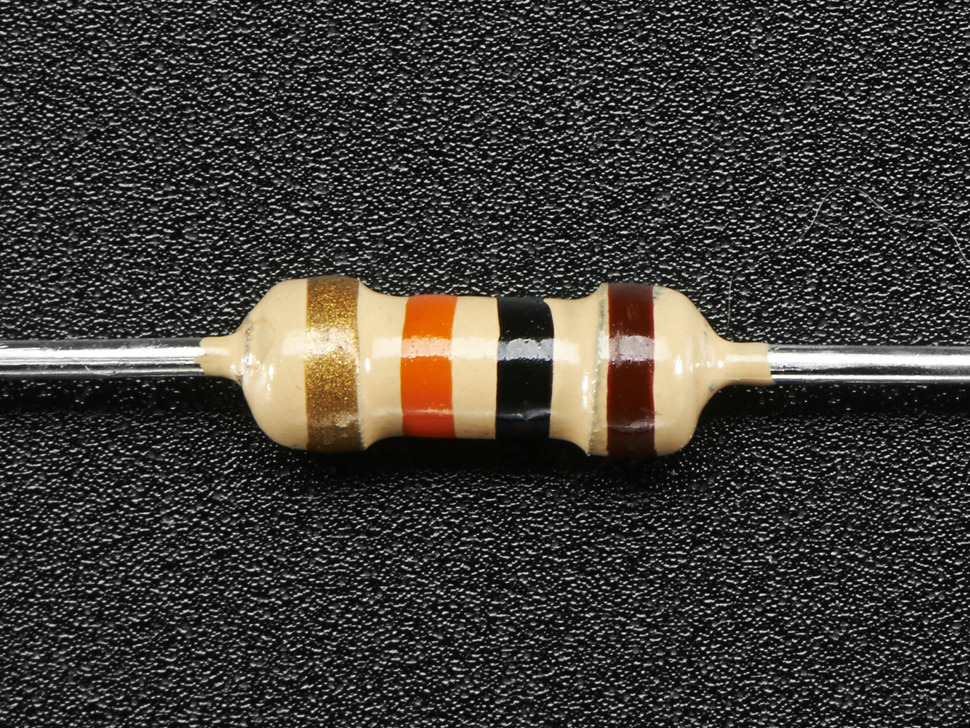
10k resistors, these are needed to bridge between the outer pins of the MOSFETs.
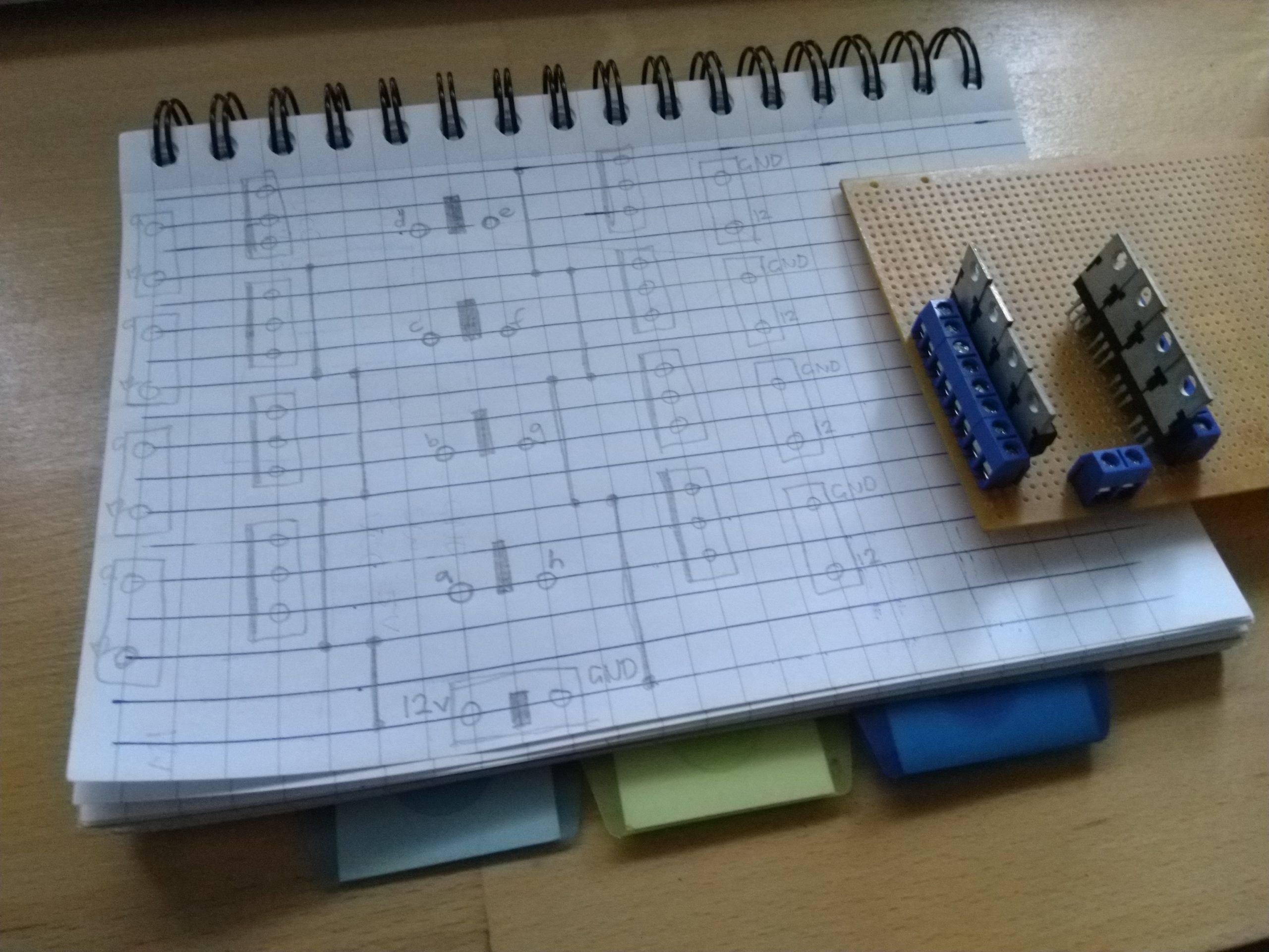
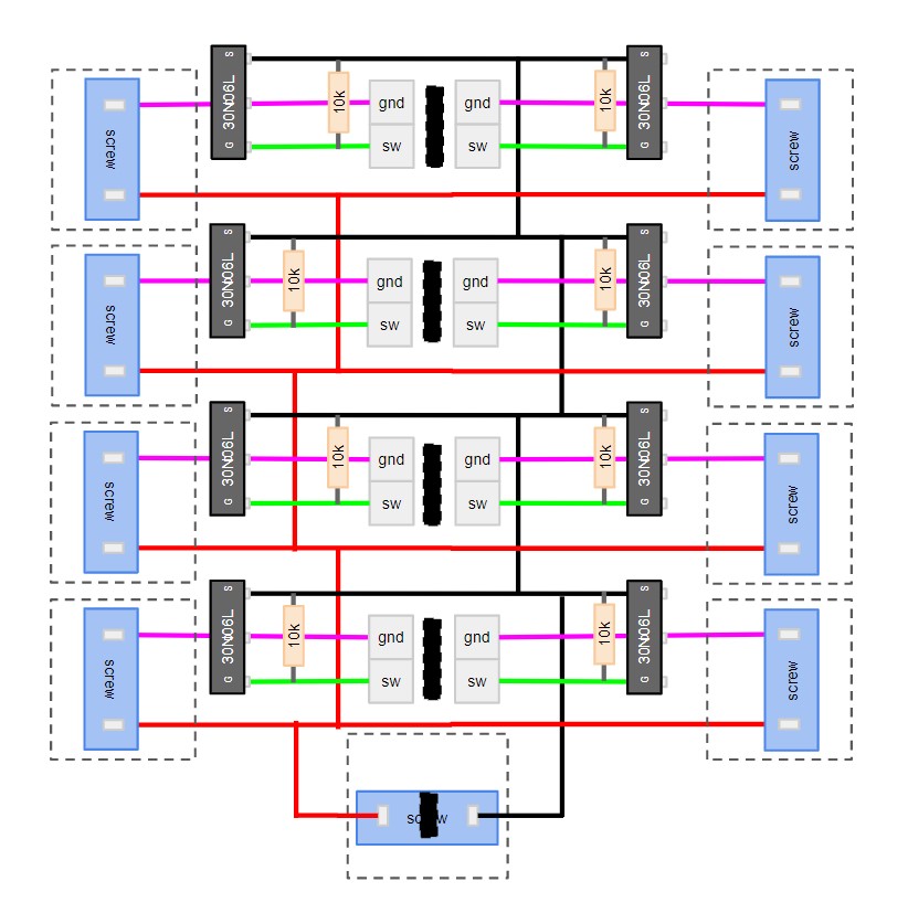
Board design
With all the parts in stock it’s over to designing a board to house them. I am going to piggyback on the 16 channel shift register board I used for the 16 segment displays, meaning this board won’t need the shift registers. Veroboard doesn’t seem to come in giant pieces so a 16 channel board is out of the question, but I can build two eight channel boards instead in a compact manner.
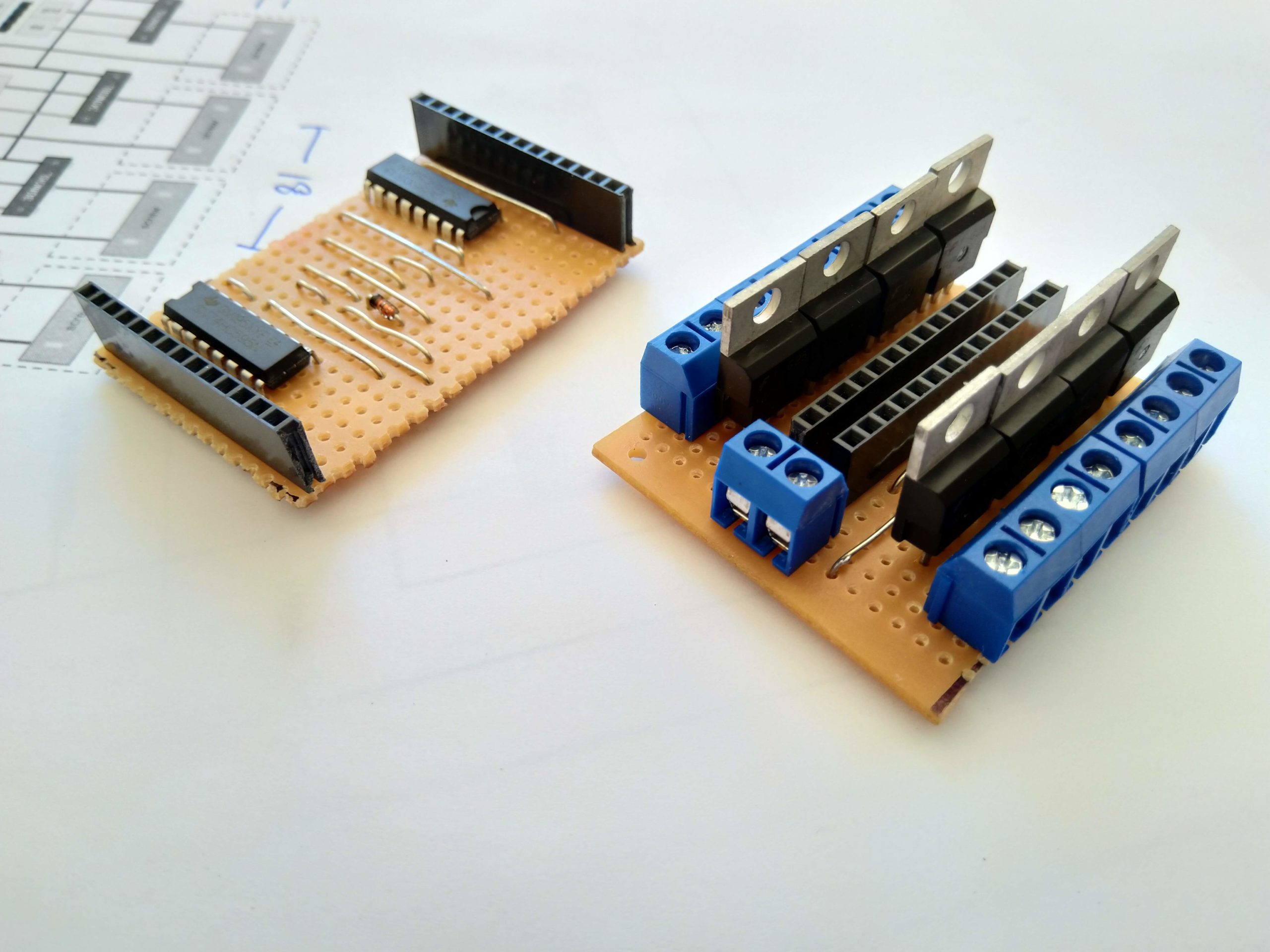
Now it’s over to soldering one of the shift register boards from the giant alphanumeric display project, and one of the above boards to see if the theory works.
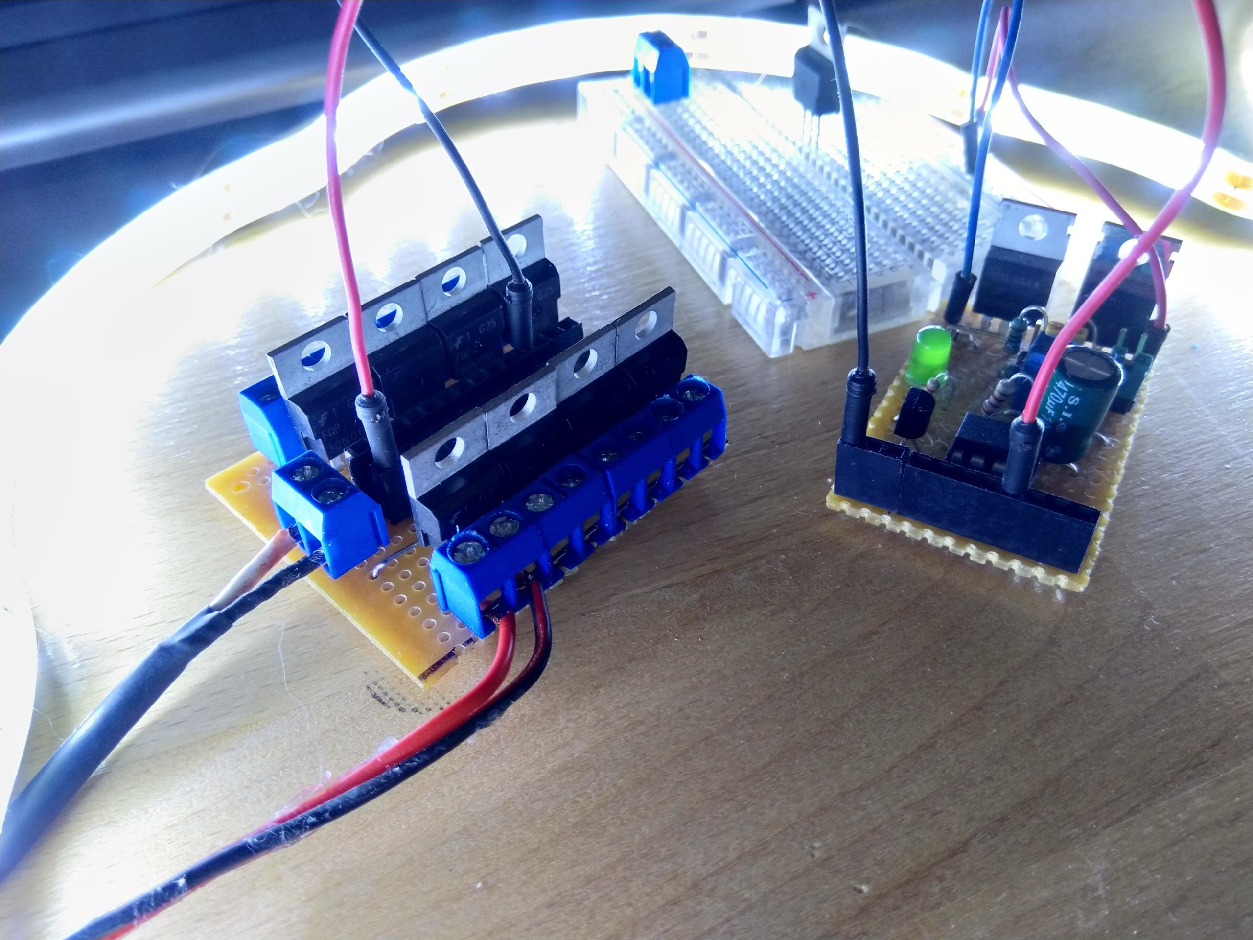
Initial boards soldered
With a MOSFET board made, it was time to test the theory at this step to see if it was too crazy. After a few goes I realised I was missing the resistors which caused the lights to just stay on or flicker randomly. An emergency addition of resistors across each MOSFET solved it, with a ceremonial lighting of a 12v led strip!
Remaining boards completed

Another day another couple of boards done, which are a new controller board in the latest revision, and a second MOSFET board. These are all the pieces we need now to do a full scale test.
More test preparation
The end design for this project calls for 18 tiny led strips in addition to others. The 12v led strip I have can only be cut in to 3 led segments. So I worked out I could cut those, solder them, and use them to test all the boards and connections are good. So off to soldering I went.
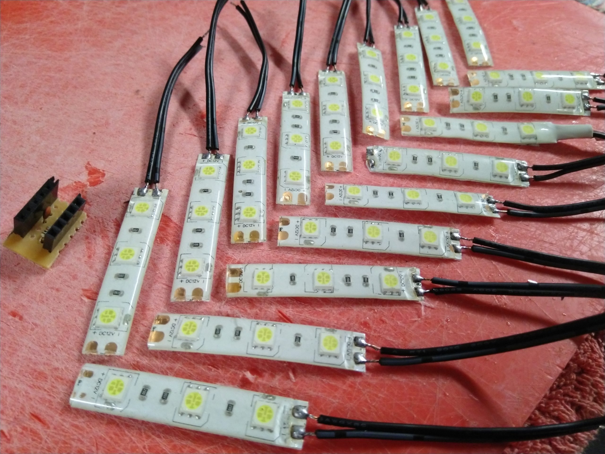
I also realised I had forgotten the components to do the shift1 trick that I had used in the giant alphanumeric display, so I made a small board to house those also as shown in the image.
Initial testing
This is showing a lot of small issues. At first the code was old and incorrect so after solving that I had a basic pattern showing.
Hooking up the second board however wasn’t so successful. There appears to be two flaws – one shift register seems slightly faulty which is something I have discovered in the past. And some of the MOSFETs seem like they are either leaking or joined together.
Also in my testing I managed to destroy the 5v supply. Sadface Emoji.
All boards tested
I went through all MOSFETs testing them manually, and the shift registers and determined that one shift register could be replaced, and two MOSFETs along with their corresponding resistors just to make sure.
With this painstaking operation done, it was time for a full 16 channel test at the correct voltages. I had burnt out my previous 5v supply, so I am now using another one of the ATTiny85 boards to regulate the 5v down from 12v for the shift registers. The controlling ATTiny85 is running at 3.3v.

It all works normally now across all the voltages and boards. There is one blip you can see on about channel 14 at the top left, but this was present prior to the shift register changeover so I believe it’s a code issue. Also the pattern is meant to bounce the led back the other way which also indicates something is wrong in the code. But for the electronics we’re looking good!
Why not just run the ATTiny85 on 5v?
The reasoning for the 3.3v is so that I can interface directly with an ESP32 or ESP8266. That will allow me to fetch the light patterns from a webpage or API.
Code issue solved
The odd blips that were appearing in the last test did turn out to be a code issue. Slowing it down revealed some segments were turning on at the same time, and the pattern when reversed had the same glitch just mirrored. Turns out I had the data being sent to the shift registers off by 1 bit. With that bug sorted I had all 16 channels working well. Testing it on the bench for a couple of days uncovered another leaking MOSFET or resistor but with the looming deadline for this project I’ll reduce it to 15 useable channels and fix it after.
What’s next?
Now that the test is successful and I know how many useable channels I have, it’s over to designing what this is for.
My DIY skills will be put to test in the next couple of days.