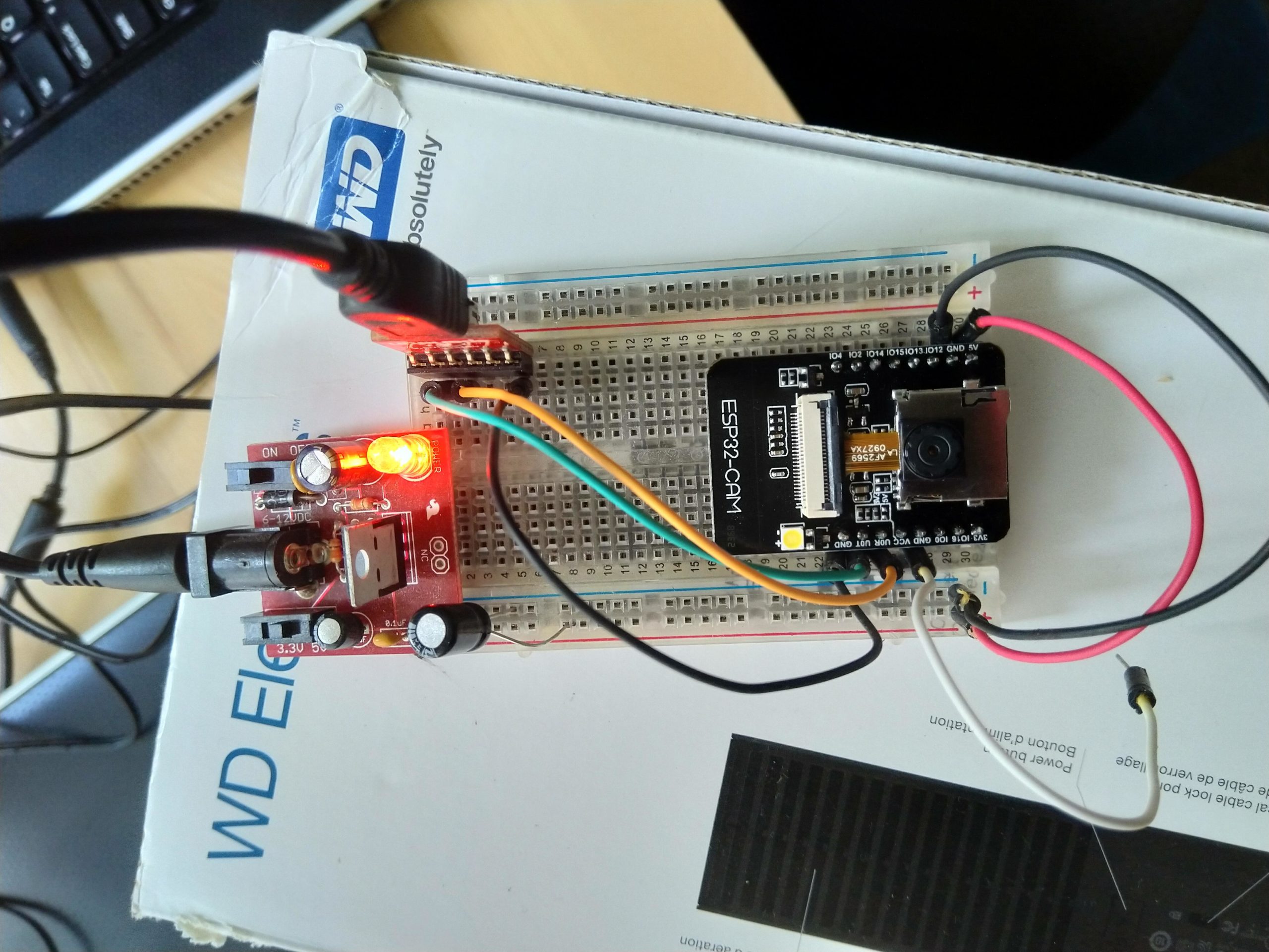
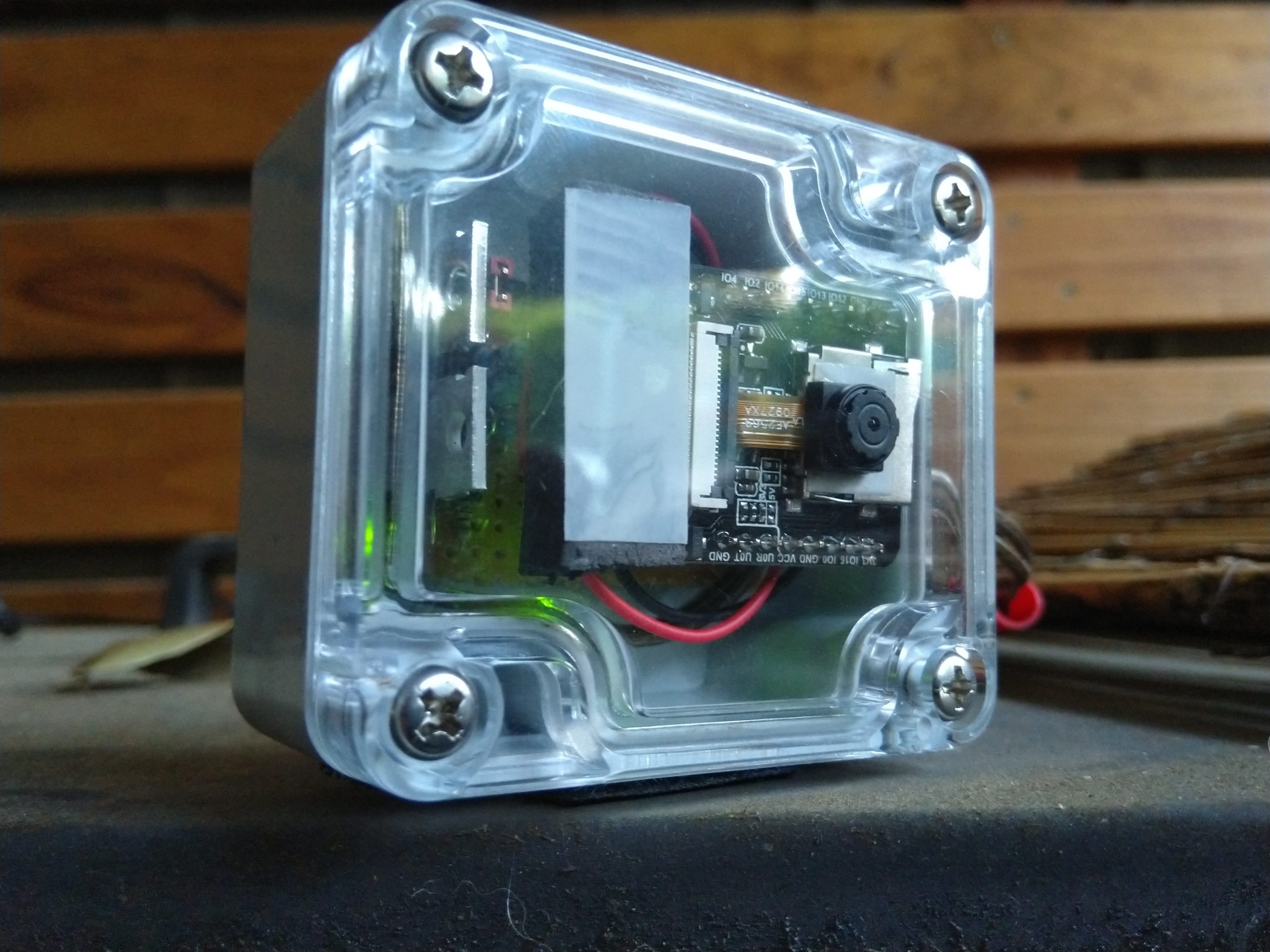
The initial concept behind this was to solve a simple timing issue. I was tinkering with the esp32-cam boards getting it to act as a basic webcam, with a webserver pulling the image directly from it each minute.
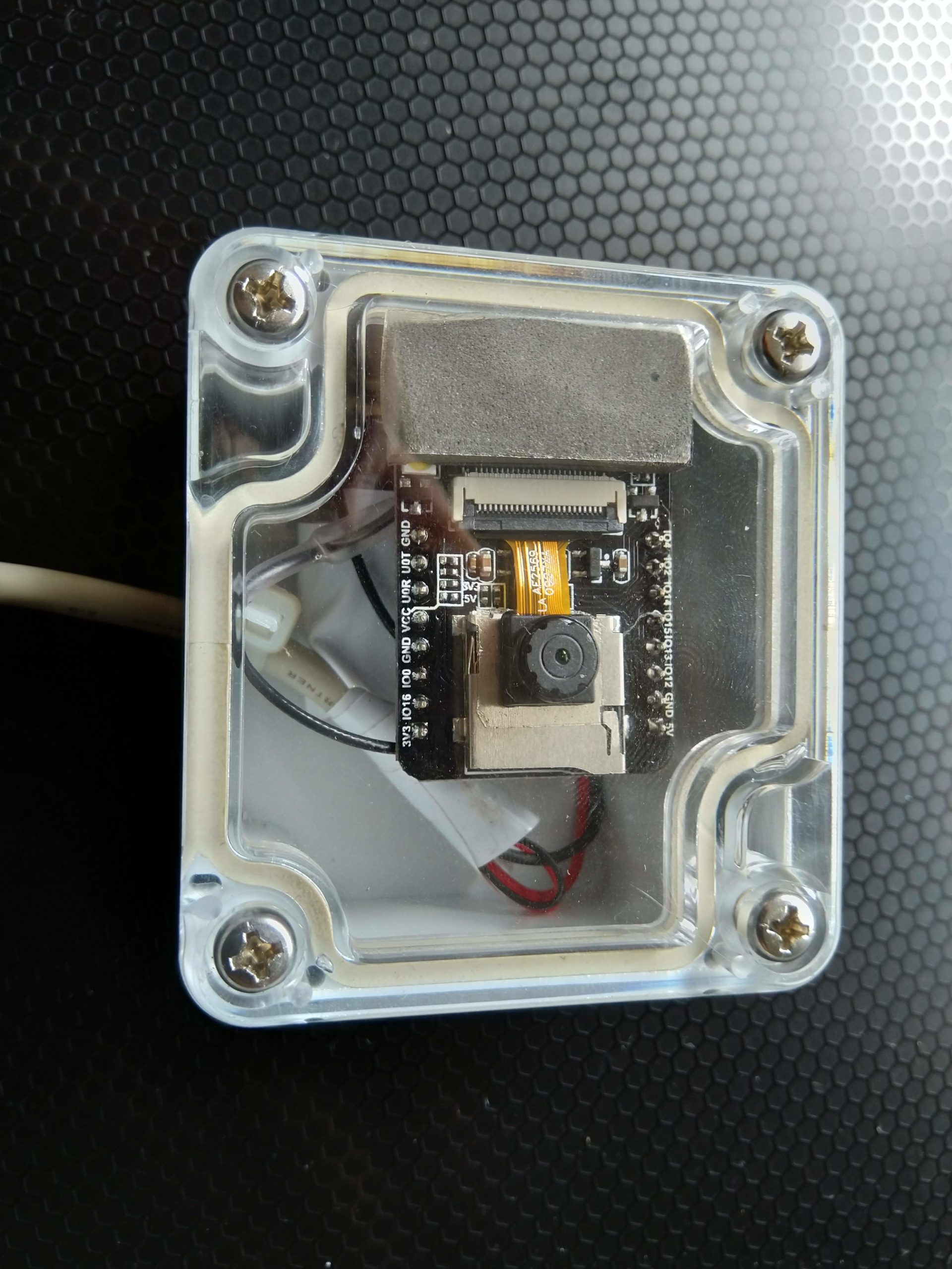
This was all programmed and assembled in a box as pictured, but after running for a period of time (from hours to a few days) it would stop responding to web requests.
The solution ended up being a power cut. The quick answer to this was to put a mechanical timer with a 15 minute block disabled on the power supply – a trick I have used in the past for stubborn PC’s. I know it isn’t ideal but it works.
This meant the camera would at least reset each day but I was losing 15 minutes of pictures. Not ideal and not scalable.
After capturing these images though it got me thinking, why not flip the process – only power the camera up for each photo, and get the camera to upload the image itself? That would give it the best chance of working each minute with a few other benefits.


Flipping the process
I needed to give the esp32-cam enough time to do the following:
- Boot
- Connect to wifi
- Take a photo
- Connect to the web server
- Post the photo
- Disconnect from the web server
- Disconnect from the wifi
- Wait forever
This was timed at anywhere between 10 to 20 seconds depending on signal. There were two clear benefits of this approach:
- Start with a cold boot each time meaning no memory leftovers to contend with.
- The camera would be pushing the image itself, meaning no firewalls and no port forwards, allowing it to upload from anywhere on the planet on any internet connection.
- The power off cycle reduces power usage considerably meaning this could be expanded later on for super low power usage.
555 timer
I had never explored 555 timers but knew they would do the job of a rough 40 second off period, and 20 seconds on. This would result in a photo roughly each minute.
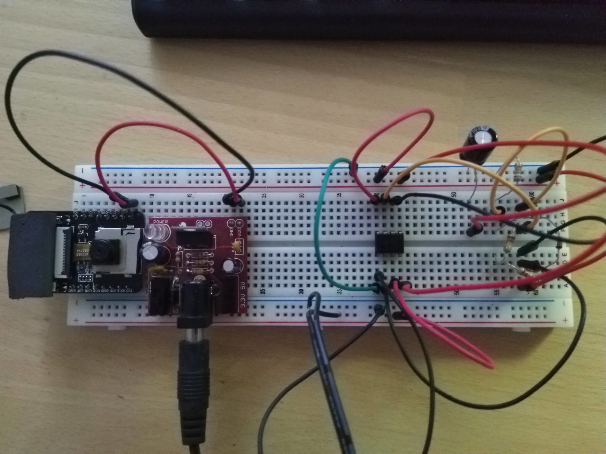

This successfully turned the esp32-cam in to a self-uploading device and solved the unresponsive issue. This required a relay however as the board is picky on needing almost exactly 5v and a decent amount of current when everything kicks in, so a transistor wasn’t suitable.
After testing this for a couple of weeks and listening to a click twice each minute I wondered why not use an actual programmable chip to do the timing rather than a mix of capacitors and resistors?
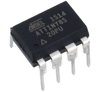
The ATTiny85
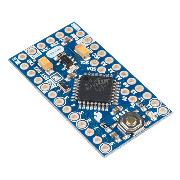
I was already familiar with Arduino and its Pro Mini 3.3v compact boards from a project a few years prior. So why not go one step further and make my own board based on an even smaller chip.
I had read about the ATTiny85 chip and how they have incredibly low power usage when put in to deep sleep – perfect for something that will spend most of its time in the off state. All I need is to create a somewhat regulated power supply for it, and replace the relay with something less clicky.
Initial design
I wasn’t going to go to all this trouble for a simple timer to switch a camera, it had to be modular with as many uses as I could squeeze out of it.
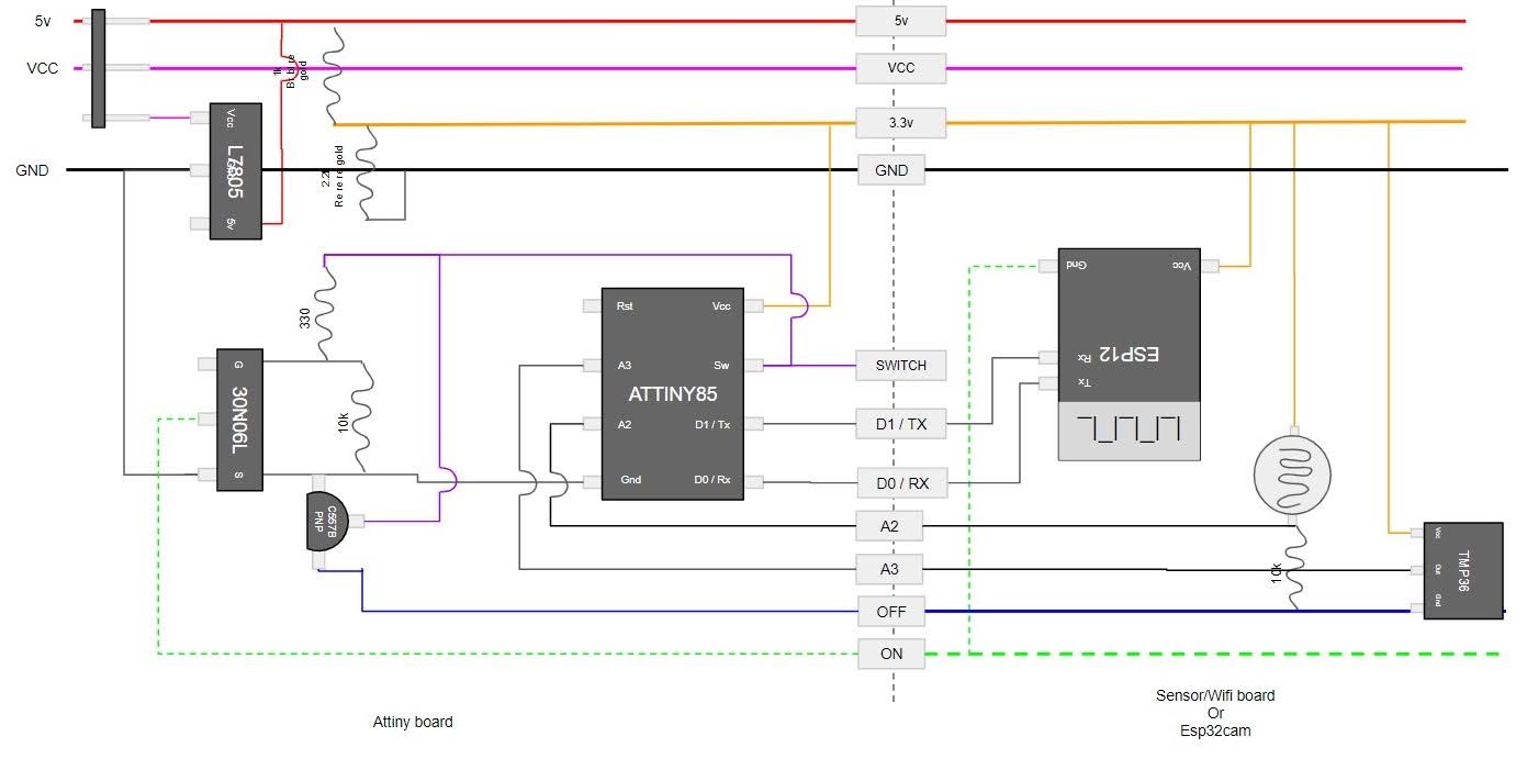
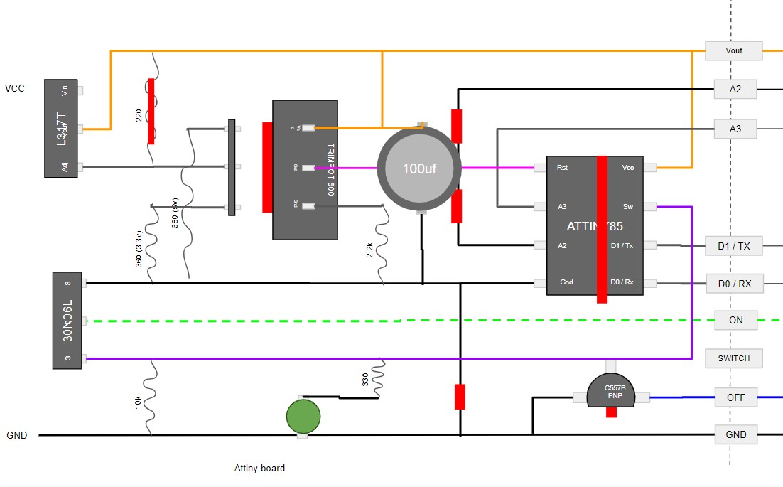
The first issue was the clicking relay – this was easily solved by using a 30N60L negative channel MOSFET which would switch a ground on and off. When in the off state, a transistor would allow an alternate “off” ground to be used with a slightly lesser voltage.
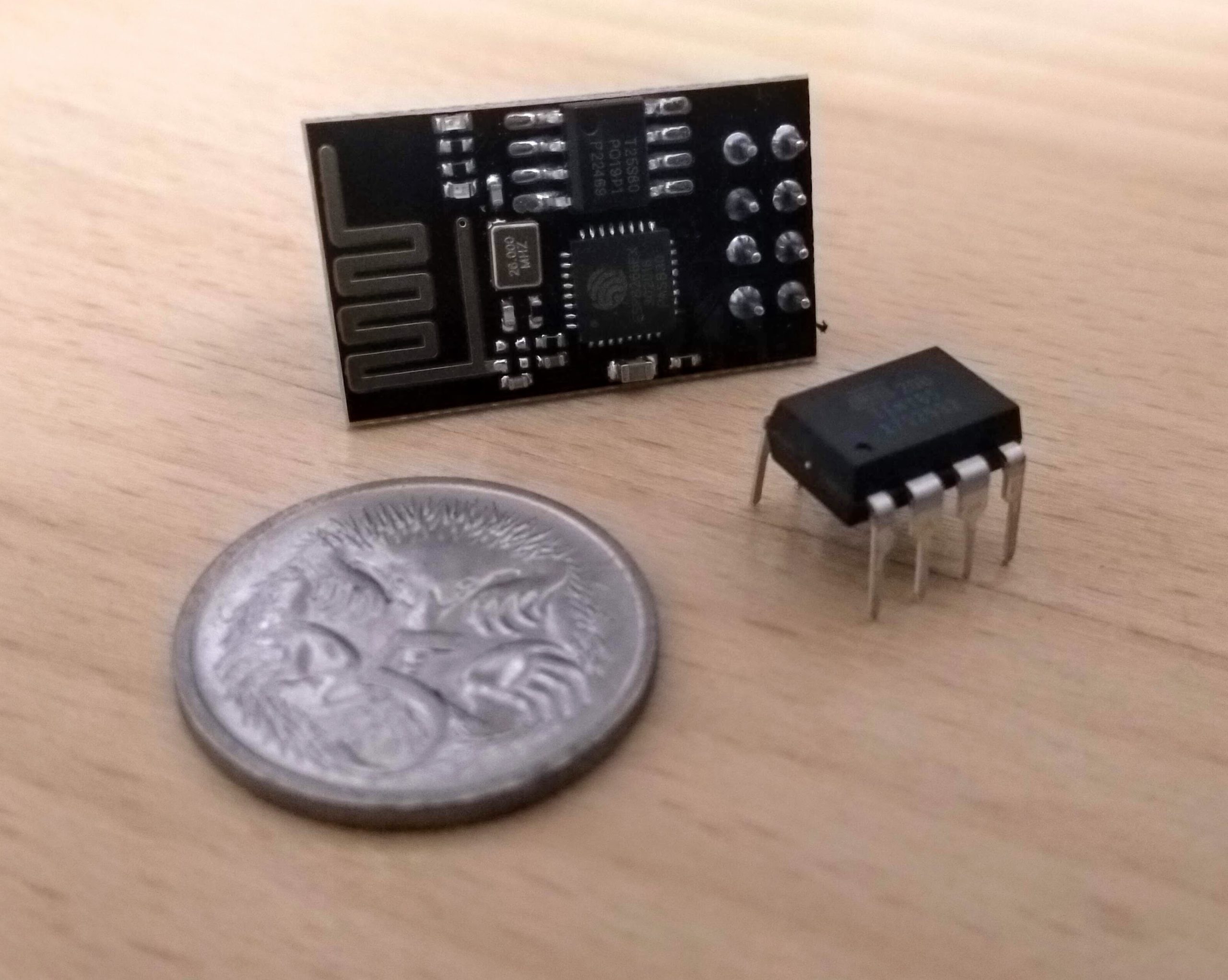
Second issue was the power supply. With the “off” ground it allowed me to run sensors and not just a camera. These sensor values would then need to be pushed up to a webserver by way of an ESP8266 or ESP32. Each of these run on 3.3v instead of the 5v that the esp32-cam does. So this would need to be able to run at both. Luckily the ATTiny85 will accept anything above 2.7v.
And just for a challenge, it all had to fit inside a tiny jiffy box I had leftover from a previous project.
I tried a few ideas with this. A resistor divider but it didn’t create much current. Two different chips – one for 3.3v another for 5v, also with a resistor divider to still create 3.3v from a 5v regulated supply. However I soon realised my breadboard power supply used a single chip to provide both 3.3v and 5v with just a switch.
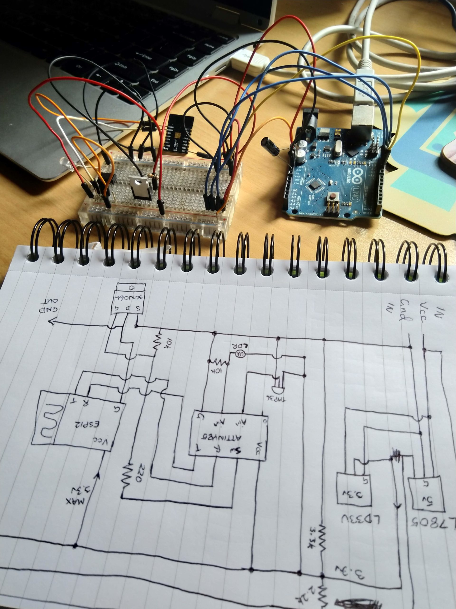
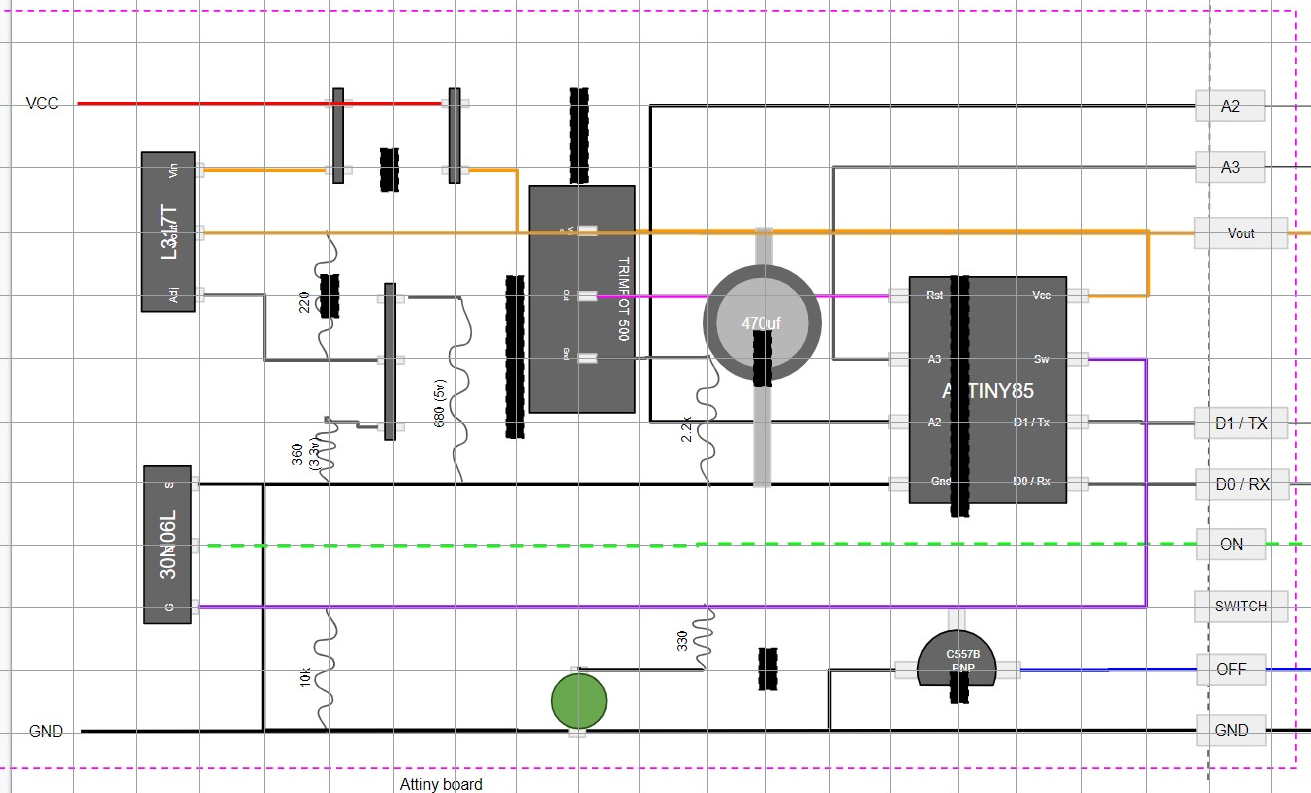
The adjustable regulator called an L317T changes its voltage using resistors. With a carefully placed jumper it meant we could run this board on anything from around 4.7v upwards, and have clean enough 5v and 3.3v depending on what peripherals we were using.
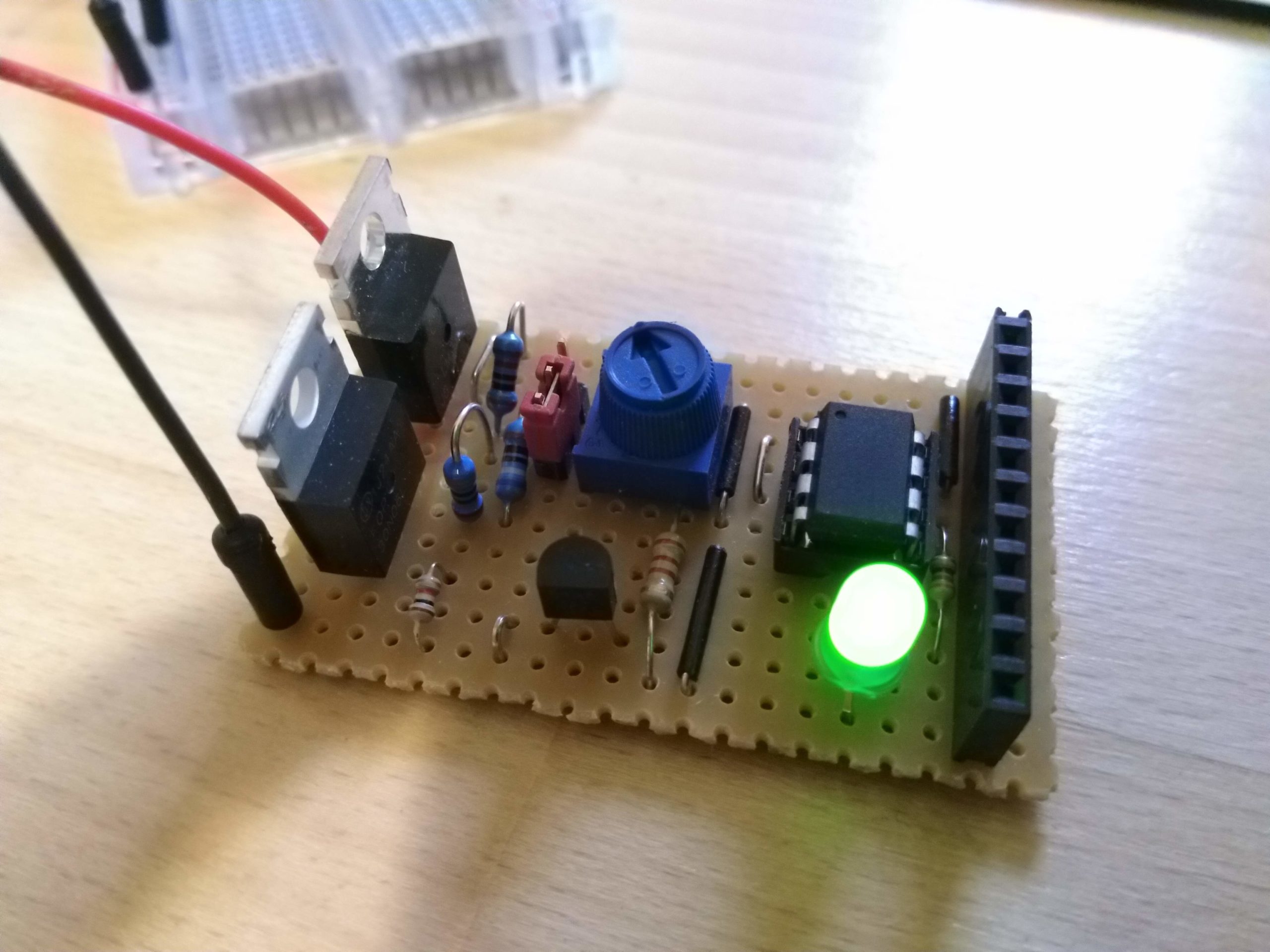
With this decided, and a variable resistor to adjust an analogue pin for the on/off value, we had our initial timing board.
Current drain
I discovered fairly early on that when the esp32 cam or plain esp32 powered on it would occasionally steal enough power from the ATTiny85 to cause it to get confused.
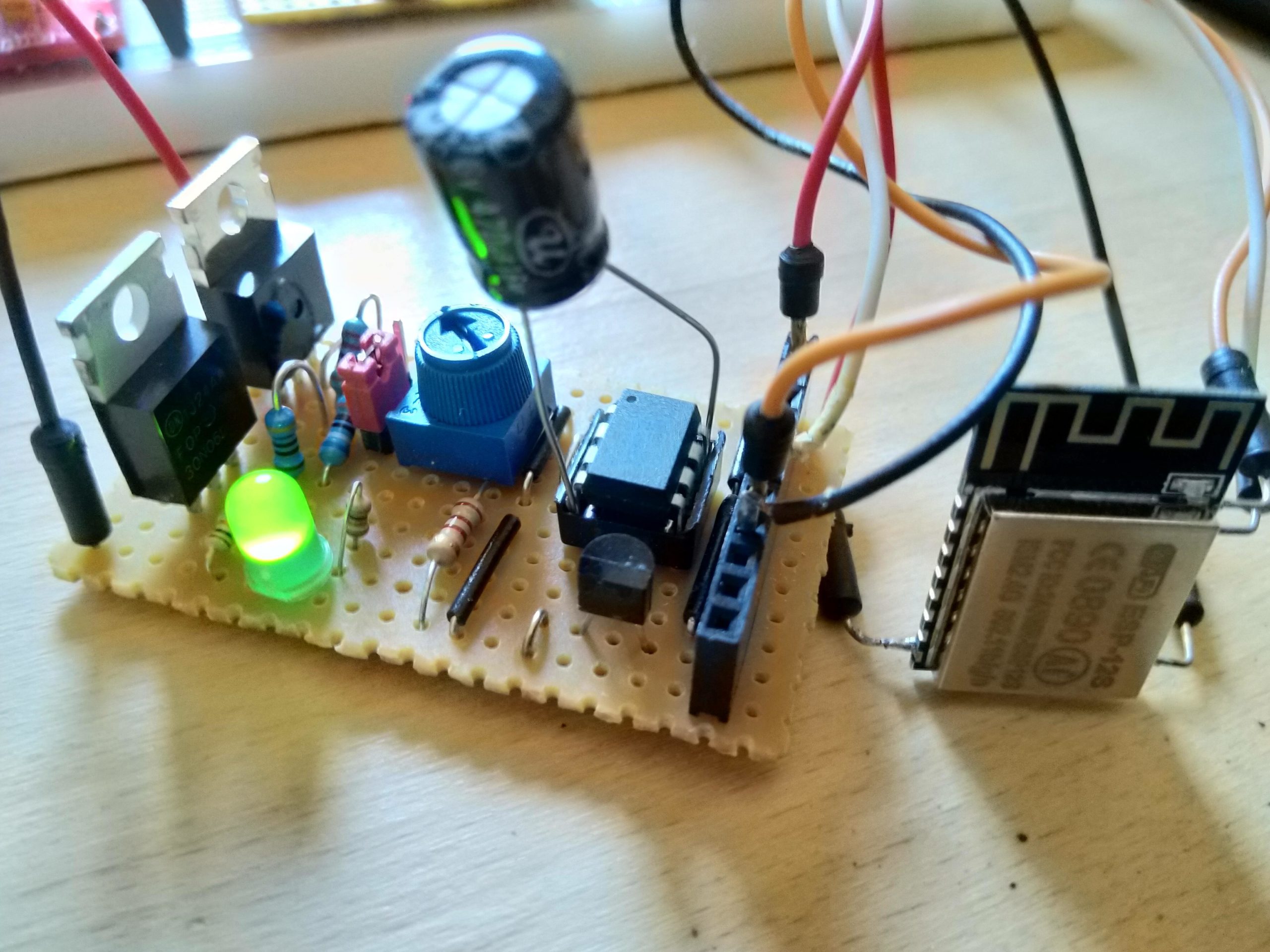
I tried a number of capacitors across the regulated VCC and GND and had some success, so I incorporated this in to a further revised circuit.
A few of these were made which was just enough to trial a few theories with. At this point I was working on the web server a fair bit to get it to receive the values.
Mass production
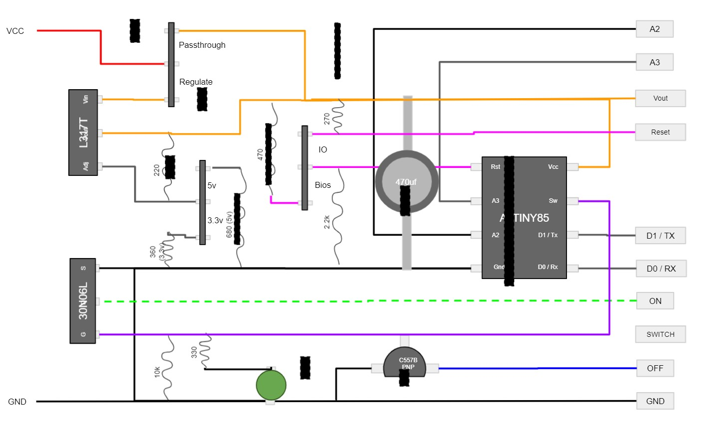
Everything started to look a little more stable. So further revisions were made to the circuit to accommodate those changes. One of the main adjustments was to allow the VCC to bypass the regulator in the case that we are being supplied 3.3v or 5v already. This would allow us to run 5v off a USB adaptor if needed by changing the position of a jumper, or 3.3v by keeping the regulator on. The capacitor was also changed to a larger one to allow for a few edge cases that continued to steal from the ATTiny85.

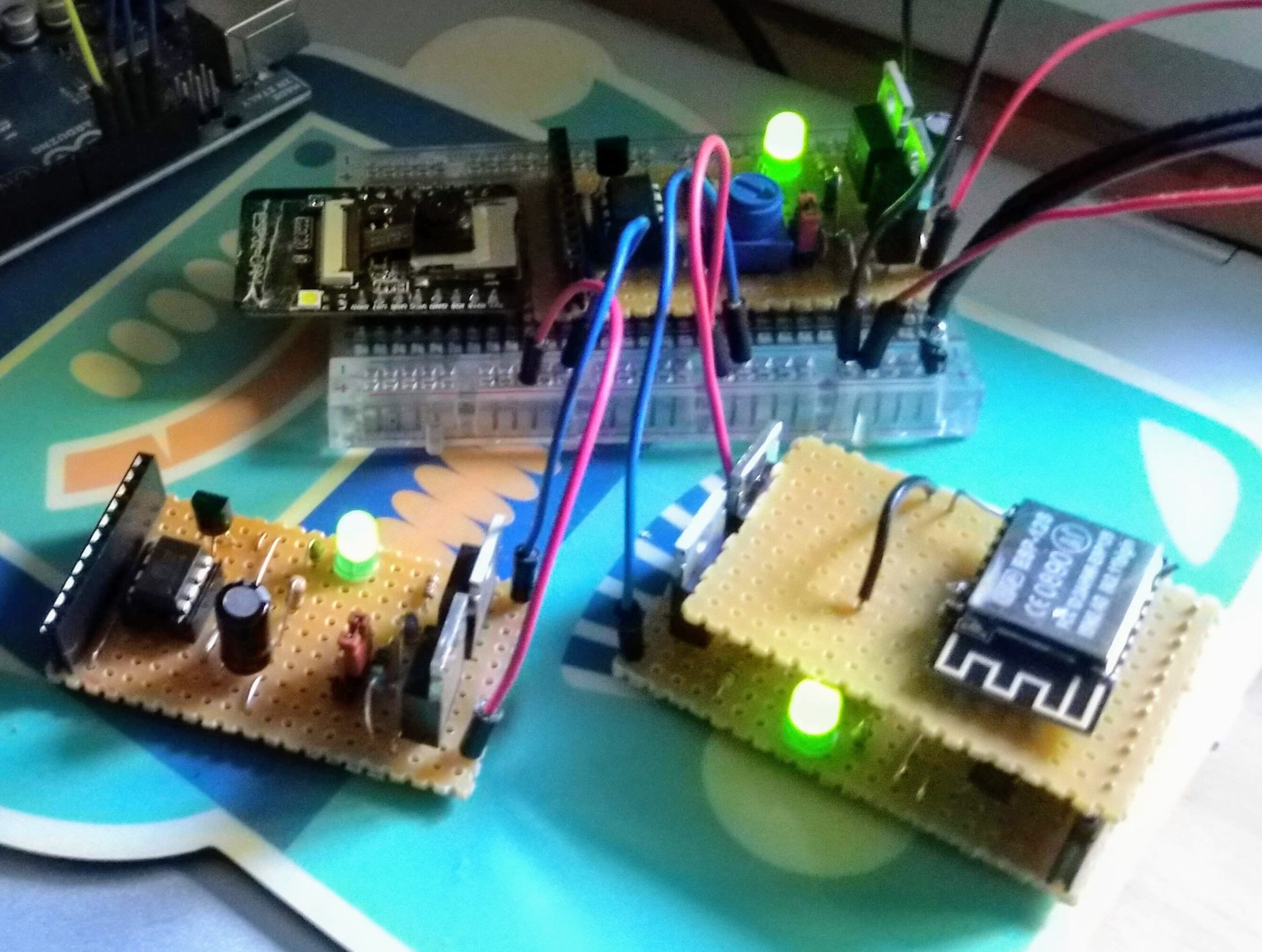
Seeing if it all fits
Of course the original plan was for a timer circuit for a camera, so I got all the settings put in, wired it all up and stuck it in a box to let it run for a while. This turned out fairly successful but showed a fairly decent issue along with a possibility of expanding this further. We have a full 8k of code space to use + wifi + 4 pins we can read or trigger – lets not just waste that on a simple timer.

Putting the reset pin to use
I wanted a way to store the settings for these boards outside of the code itself. I looked in to a separate EEPROM chip but these cost more than the ATTiny85 itself which already has 512 bytes of EEPROM. It seemed crazy to run two ATTiny85‘s. Then there’s the esp8266 which also contains EEPROM but then I need to power it on in order to read anything, and not every board needs wifi. It was best to use the memory in the chip itself as it’s not used for anything at this point.
I realised I could use the reset pin as long as it stayed above 2.7v. This gave me 0.6v of useable space to play with. If I created a resistor ladder I can read numerous buttons placed on it such as a keypad. So why not have this so when it powers on it checks if the reset pin was down at a fairly low level (2.8v for example) and make it show a sort of bios – similar to pressing a key when a PC starts up.
There isn’t a lot of code space on this chip so it would be a simple key:value store but it needed to be auto sorting and organising to make the best use of the tiny amount of space. A bonus to this is that during execution an application can look up any key and retrieve the value. A tiny filesystem was born, with a simple menu that triggers on the serial pins when the reset pin is just above the limit (by way of the variable resistor) – we now have a BIOS!
This allowed configuring of different parameters for each application. Suddenly we could easily run a few boards with different purposes.

Bios Corruption
An issue started appearing where if the boards were plugged in to the PC for bios settings, and unplugged from a main power supply, the bios would get corrupted. Along with sometimes the application. Even if the power was switched off and on it had a chance of corrupting. I eventually narrowed this down to the ATTiny85 running below 2.7v. This was caused by the capacitor next to it draining too slowly. This appeared to be the brownout issue I had read about while programming the esp32-cam. The fix was to burn a fuse inside the ATTiny85 but I had been wary of this as to unburn fuses I thought you needed a high voltage programmer. However I discovered this was mainly for the reset pin which I didn’t want to change.
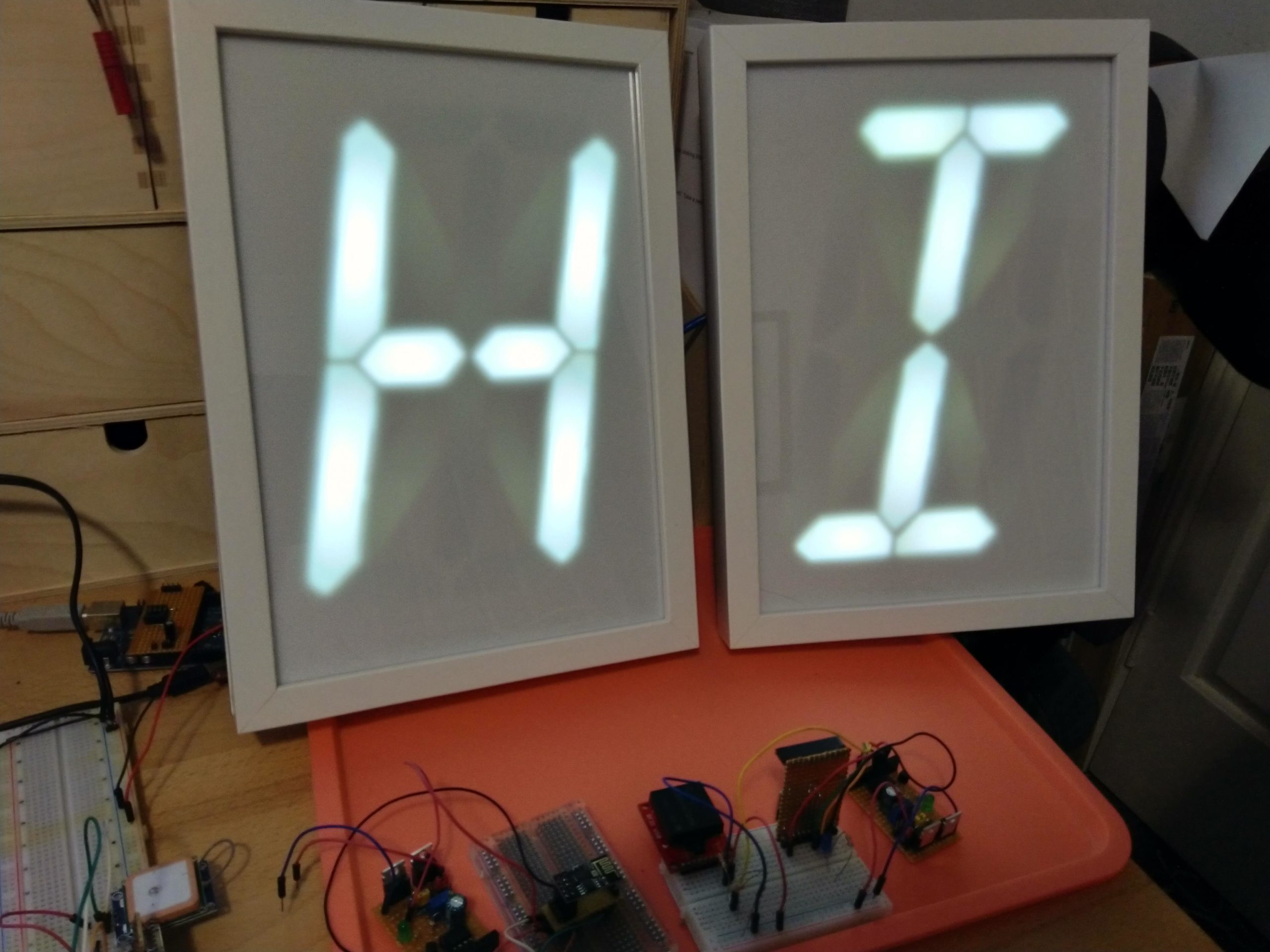
With the fuse burnt for brownout detection, things instantly became much more stable. With stability and a relatively easy way to configure it, it was time to make a project with it which ended up being the Giant alphanumeric display.
Bios switch, board cleanups
Working with this board design showed a few tiny issues and improvements that could be made.
- I changing all the jumpers in to sets of 3 to make it more foolproof – meaning the regulator and bypass jumpers couldn’t both be connected at the same time.
- The variable resistor on the reset pin was changed to a jumper, which allowed it to be a useable pin also. This made it much quicker and easier to access the bios when needed. I later on changed it to a tiny switch.
- The led and “off” transistor were moved across to allow for easier removal of the ATTiny85 chip.
These resulted in a slightly wider board but it still fits.

This board is now in a decent state, and was used for the Neon style sign using the 12v switching modules successfully. No data corruption and much easier to use over the earlier boards.
It’s now over to test how much further this can be pushed hardware wise, and design a proper board in Eagle to get it printed and look official!