Ever since seeing the music aligned christmas lights display many years ago (2009 it seems) I have been interested in how to achieve this.
Now that I have a bit more knowledge around the electronics space and a house to do it to, and seeing more recent videos it has peaked my interest in it.
I’m going to start with a few trial and error projects to see how everything behaves, and scale up from there with the ultimate goal being to create my own dedicated ESP8266 / ESP32 LED controller powering a fancy display.
And if I can achieve this, apologies in advance to my neighbours.
Initial Research
My initial research has pointed me towards using xLights as the sequencer, which can then control the light display on its own or by exporting to Falcon Player on a device such as a Raspberry PI. For the initial testing I’ll be using xLights directly.
Each led strip (called Pixels in this case) needs to have a controller. The easiest way is to go with ESPixelStick, however as I am familiar with the ESP8266 / ESP32’s through my other projects (Attiny85 board, ResourciBoard, Neon style LED sign), I’m going to try and be a little more hands on by using the basic NodeMCU platform with WLED as the firmware, as WLED contains all the necessary protocols to listen to xLights.
Note: wled is discontinuing support for ESP8266 which I’m using for most of this article. If you are attempting the same, use a decide with a genuine ESP32 module.
My research has also uncovered that 12v is best to start with if you have made no investment in led strips previously, so with the NodeMCU platform I’ll need to follow the wiring diagram on the WLED site.
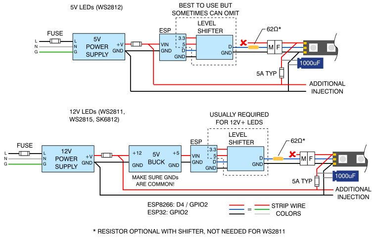
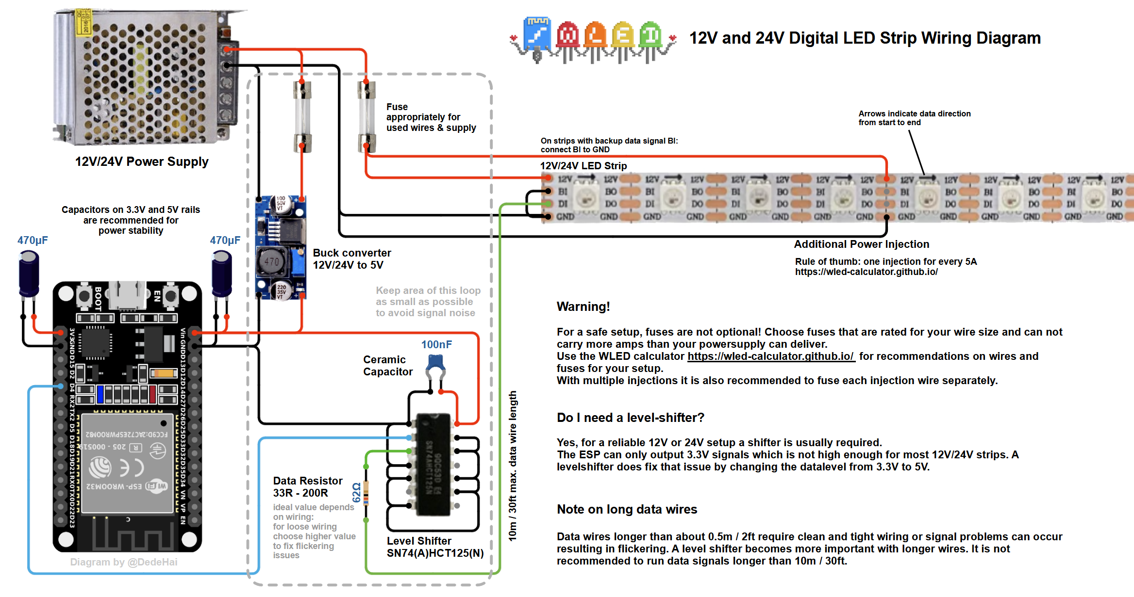
This contains a few extra parts for 12v, specifically two fuses (not really required for testing purposes), an optional 62 Ohm resistor, a 1000uF capacitor, and a level shifter to bring the 3.3v data signal up to 5v to make the data signal more reliable. The level shifter needs to be fast enough for the signal sent to the led strip – a lot of forums recommend the 74HC14 so I will try and source some.
As for led strips themselves, I an going to start with a string of RGB pixels using the WS2811 chip.
Trial Shopping List
2x NodeMCU controllers
1x WS2811 based 12v LED Pixel strip of 50 Pixels
2x 74HC14’s
2x 1000uF capacitors
Once I have acquired all these parts or similar substitutes, I’ll move on to flashing the WLED firmware on to the NodeMCU boards.
Flashing WLED to the NodeMCU boards
This is actually surprisingly easy where it really shouldn’t work but it somehow does. It’s as easy as plugging the board in to a usb port, navigating to the WLED install website, click install, choose the com port, and then follow the prompts. You should end up logged in to your WLED dashboard on the device. Easy!
I recommend loading the wled app on your mobile which can also find the boards on your network automatically. These WLED guys have done things very well.
Initial Test
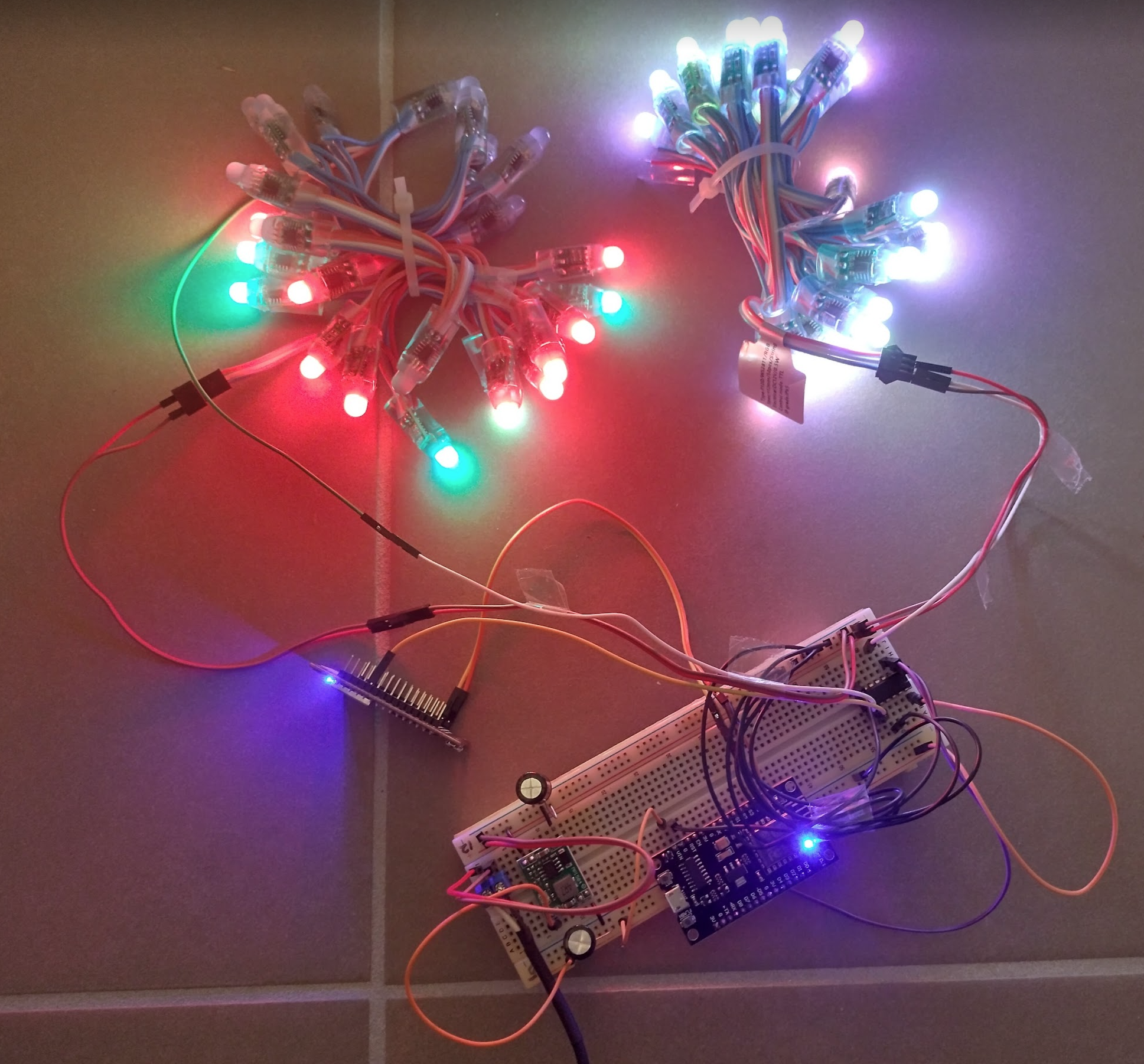
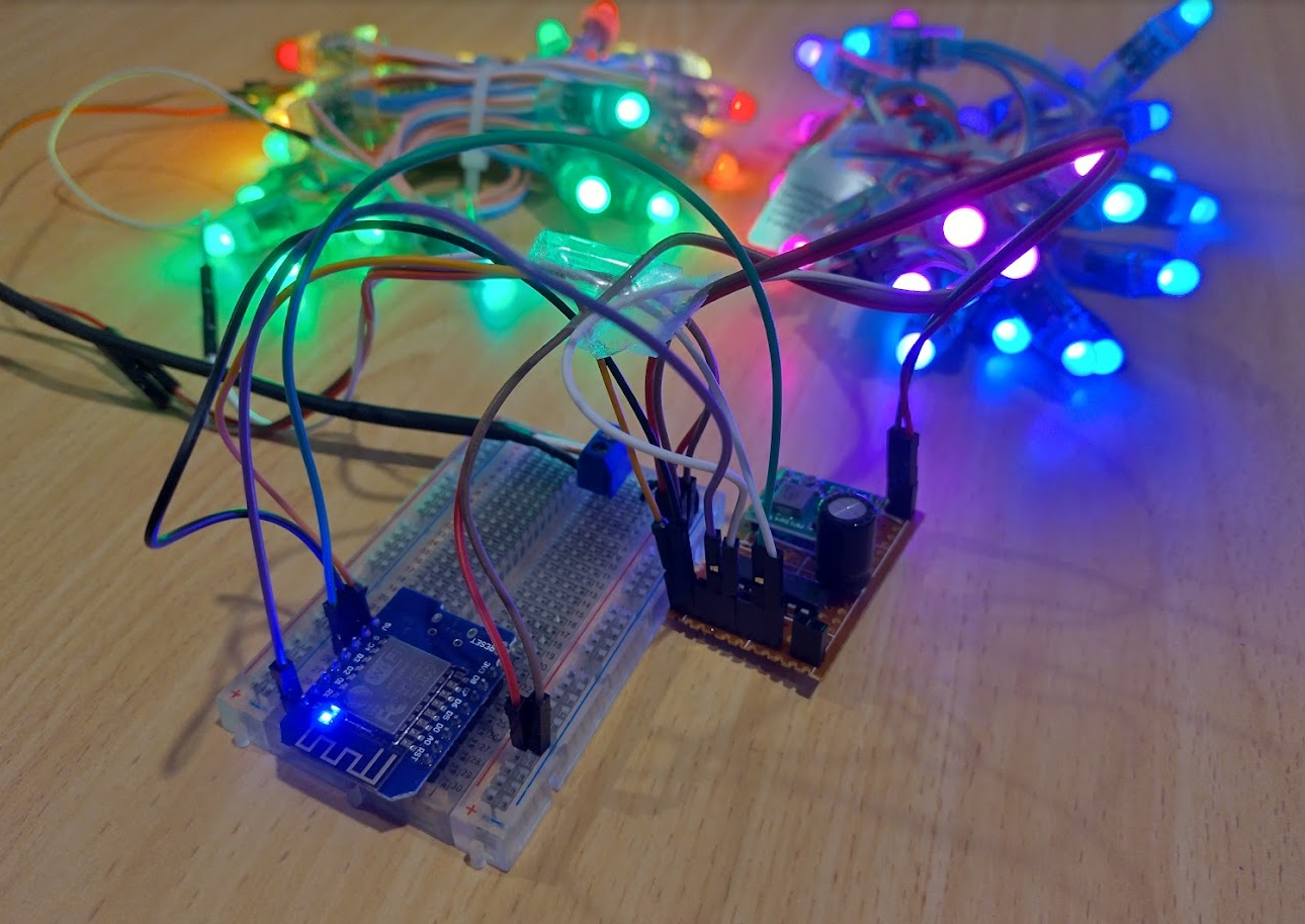
Inbetween moving house, I decided to get some things tested that weren’t too intrusive or required too many tools. So I hooked everything up with the electronics I did have on hand, and gave it a go.
It worked surprisingly well! The setup is a little different to what was suggested, so here’s the adjustments:
- 12v input
- LM317 linear regulator, adjusted to push out close to 5v. This does get hot but it was just to test the theory.
- WS2811 pixel led strip
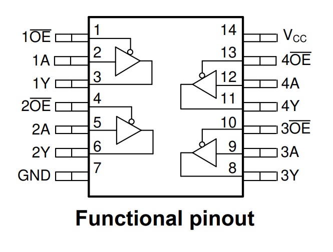
- SN74HC125N quad buffer / line driver – to bump the 3v data signal from the NodeMCU up to 5v for the lights
Pre-scale theory
I figure I can use the quad buffer for more than one light strip, and I am keen on getting the initial 50 lights cut in half to try and get two NodeMCU’s of 25 leds to work in unison. That will then prove that the circuits and chips and everything would be good to go ahead with a larger deployment.
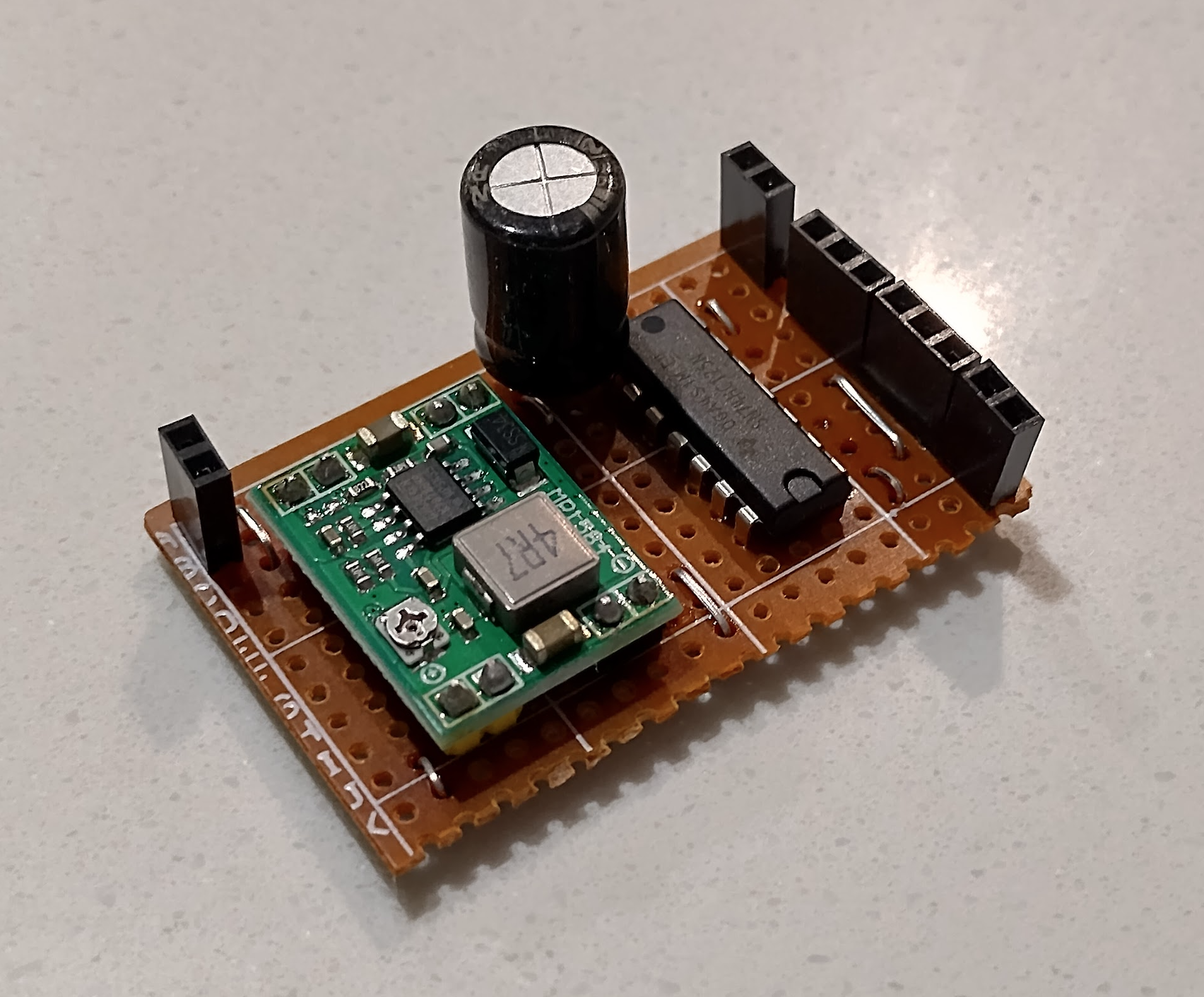
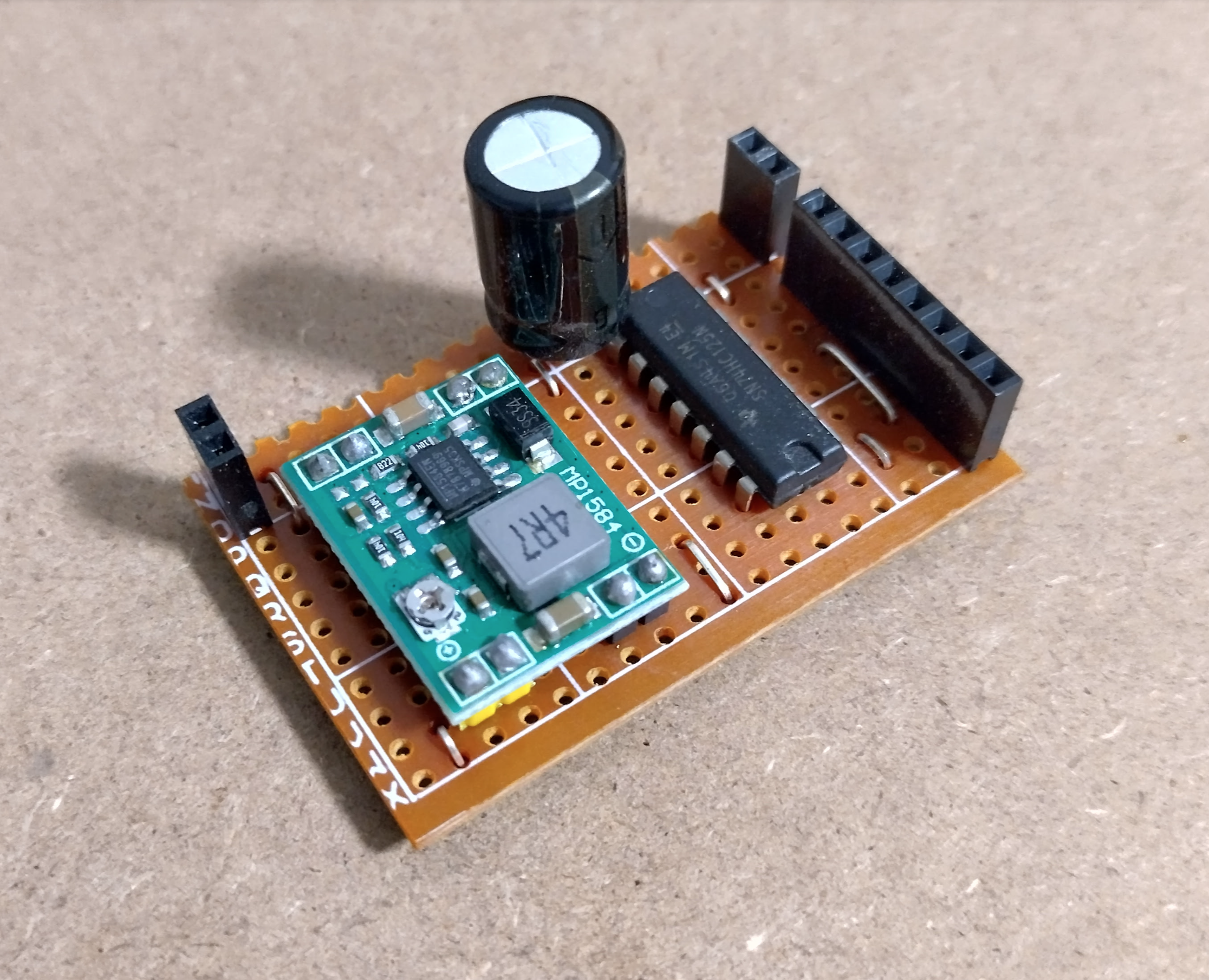
I purchased some 12v->5v switching regulators to prevent the heat issue, and got to assembling a test board.
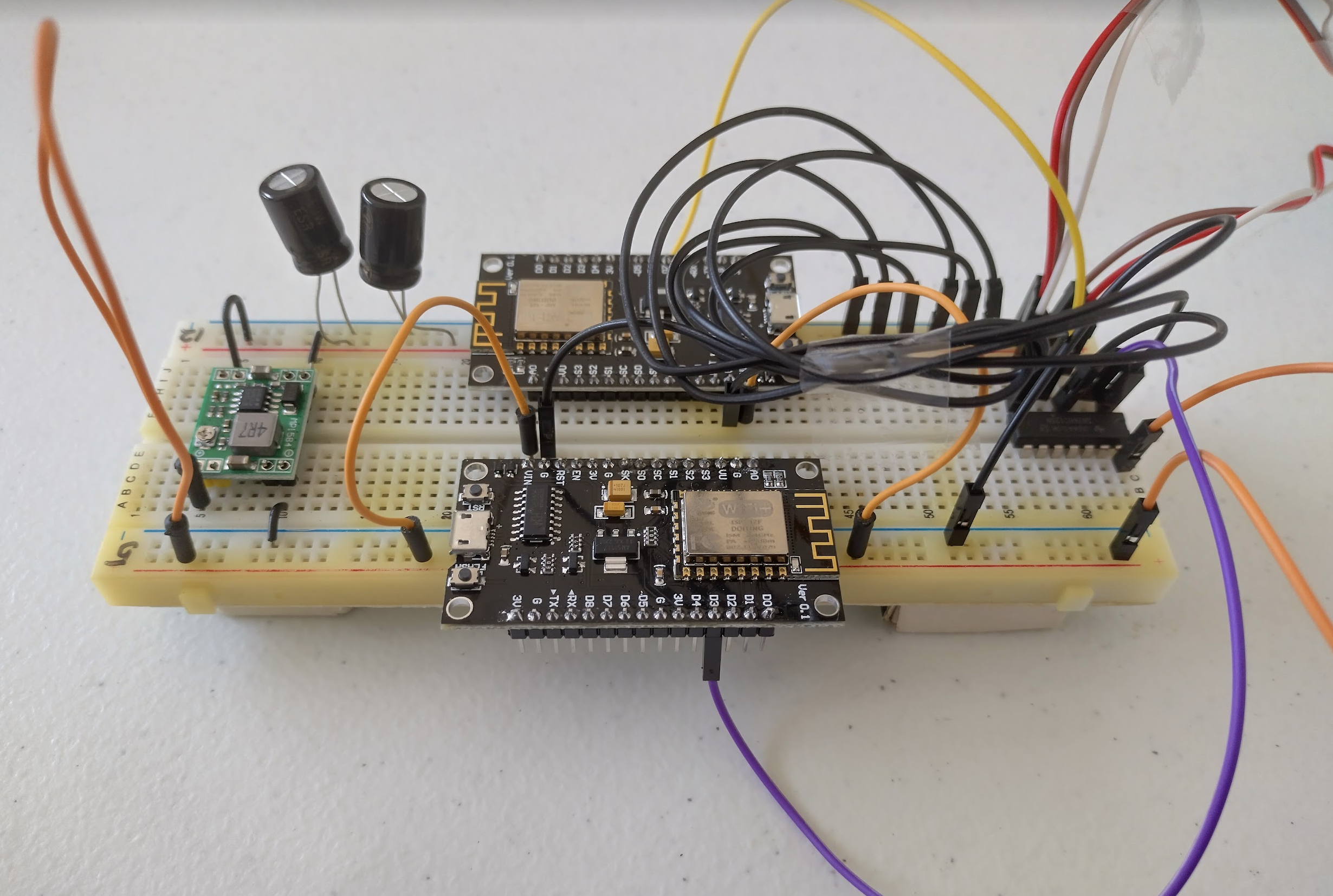
The regulator isn’t soldered yet as I have to locate my iron, and the pixels need to be cut into two 25 led strands. Once I have those two complete, I can hook all of this up and see if the power is ok to drive all of this. Then it’ll just be a matter of scaling it all up!
A bit of trial and error
After locating my soldering iron I have been able to give this a go. I separated the pixels in to two 25 pixel strips, wired it all up, soldered the power supply, and turned it all on.
A number of issues appeared immediately:
- Only one NodeMCU could be reached successfully at one time. It didn’t matter which one, so it wasn’t a hardware fault.
- Only one set of pixels would light up.
After a lot of tinkering it turned out to be these issues:
- The NodeMCUs can’t be that close together, they are interfering with eachothers WiFi.
- I had the second set of pixels wired up incorrectly to the SN74HC125N.
- The second set of pixels don’t allow the data pin to come from the other end. It MUST be from the cut end. It just didn’t want to work the other way.
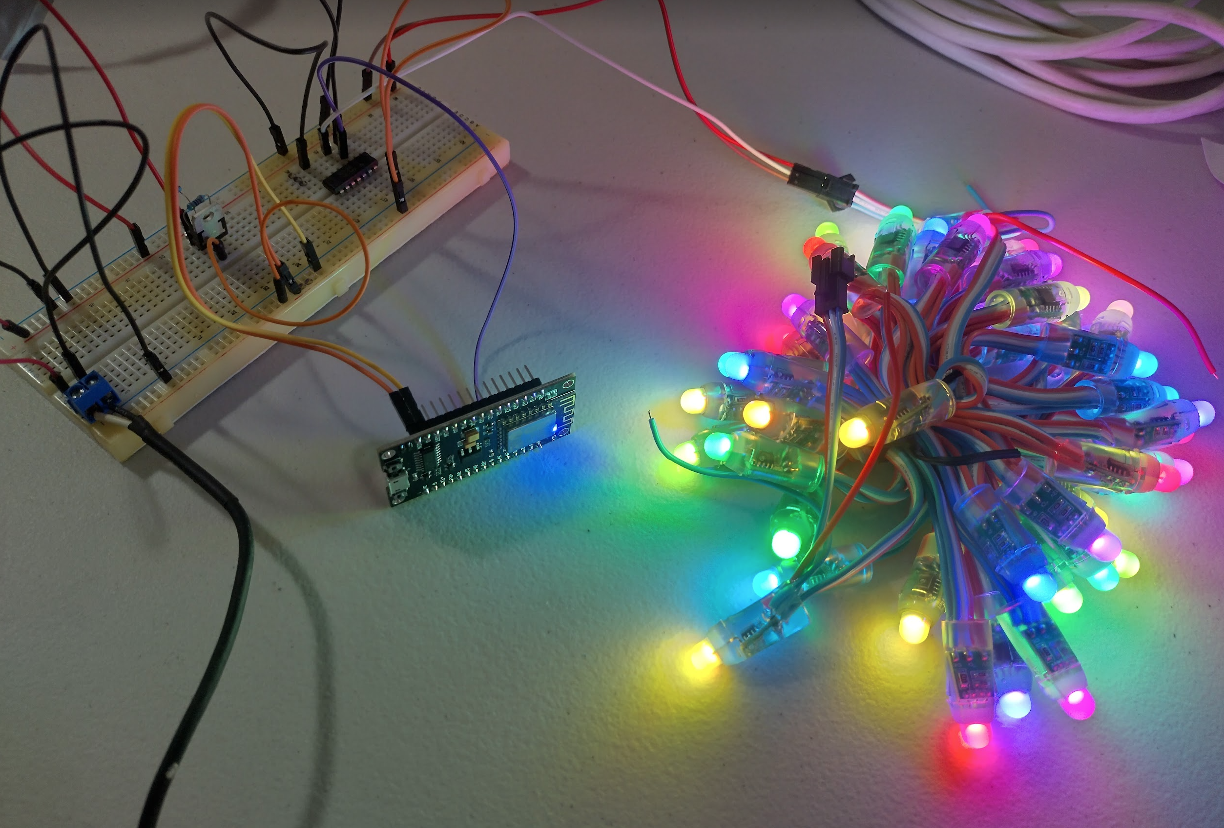
Once these were resolved it came alive!
This is showing it’s possible to control two NodeMCU’s using a single power source and SN74HC125N. It’s probably safer to just have a separate circuit per light strand however.
Now that I have two, it’s over to xlights to see if I can get them to react as though they are part of a house display. That will give me everything I need to scale it up, as the only limits should be 12v power capacity, wifi signal, and my time!
Veroboard Design
Just working on a quick veroboard layout for the two chips, where if I can source more of the buck regulators then I can make enough of these to do a bulk soldering session as this circuit seems to work.
New year, new chance!
It’s been about 8 months since the last update where christmas came and went. There was a window of a few months to organise something but I was made redundant from my job and therefore I had to refrain from spending up big on flashy lights. But I am preparing early this time to give it another go. It’s only April which should provide enough of a window to sort it out! First is resurrecting an old WiFi router, as I recall reading that this uses a lot of network traffic so it’s best to have a dedicated AP. So I dusted off an old netgear.
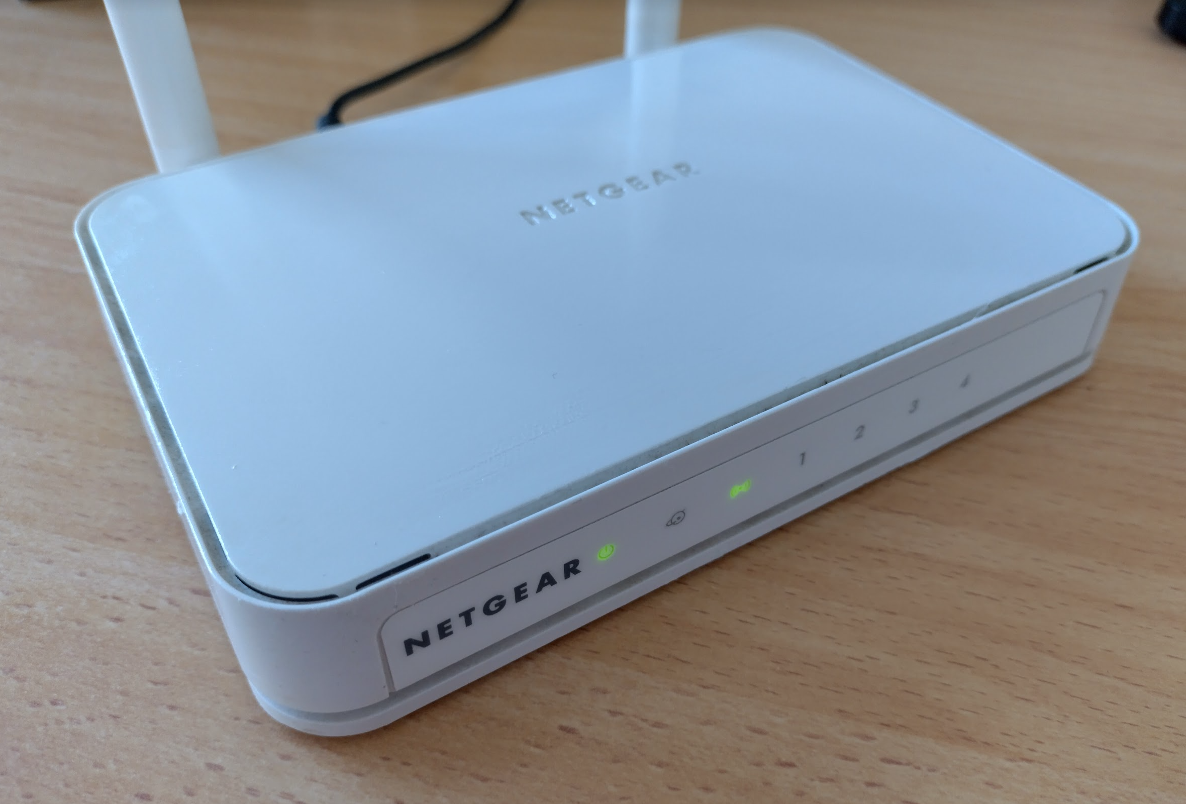
This has been updated with the latest firmware, configured, etc. ready for the nodes. I have also updated both NodeMCU’s that I had with the latest wled firmware, and set them as static IP’s on that AP. Looking good! Next is to resurrect the old circuit and try to sequence two led strips from the one board. If that works then it’s on to xlights again. Fingers crossed we can get it done this time!
Lights are back!
I have found the old circuit, rewired a few things and threw caution to the wind, and we have two strings from the one board!
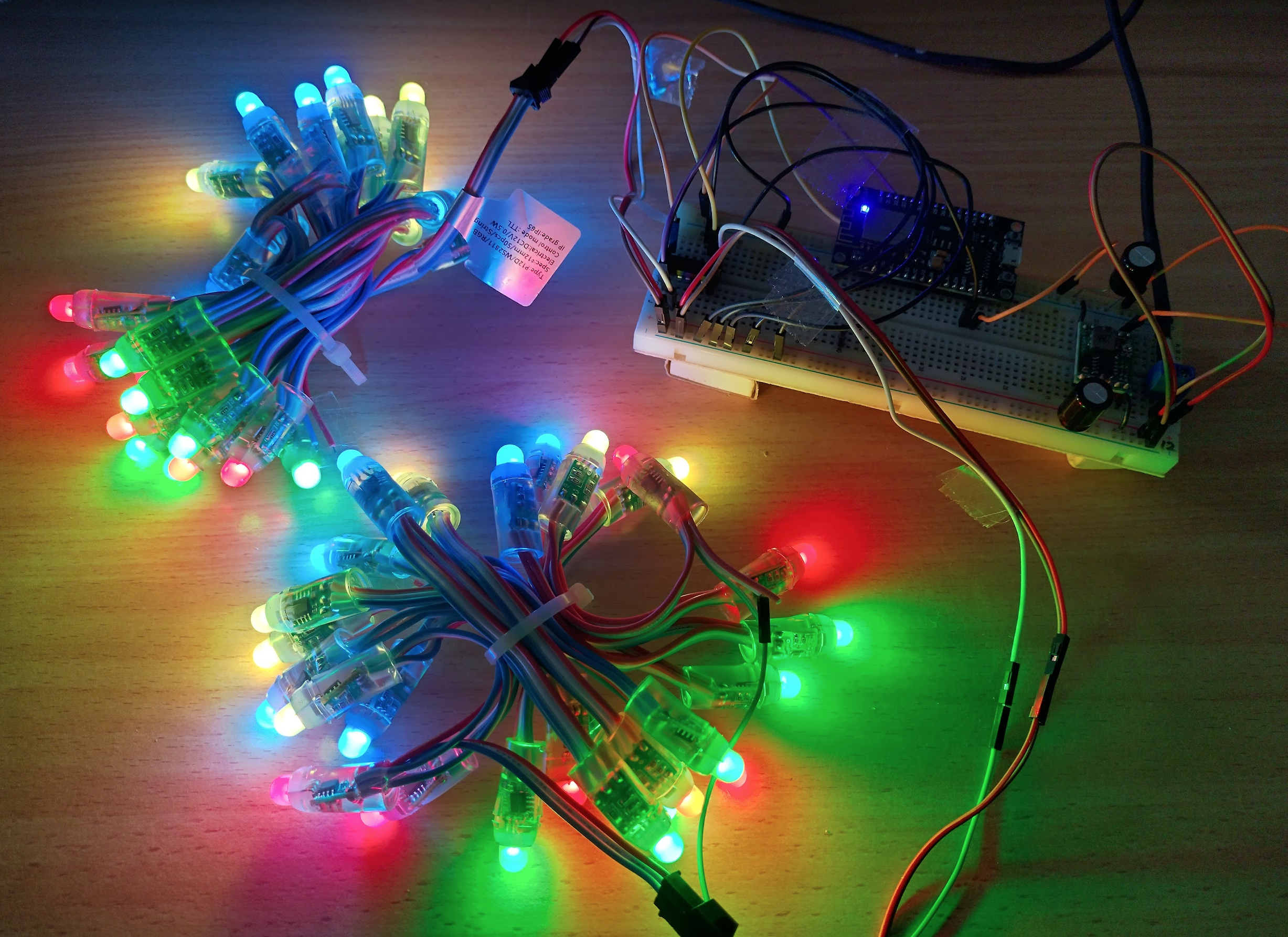
Now that this looks good it means I have the components and wiring correct infront of me. The idea is each led strip will be 50+ leds long instead of the 25 that I’m testing with.
I managed to get both strings to work as one within xlights. Some notes:
- Each nodemcu will be one universe.
- Each led consists of 3 channels (RGB). So for a 50 led (node) string, it’s 150 channels.
- It looks like it’ll be easier to work by channel number than by universe.
- To have something span across the whole house, create a group then add it to the timeline.
I think this is doable.
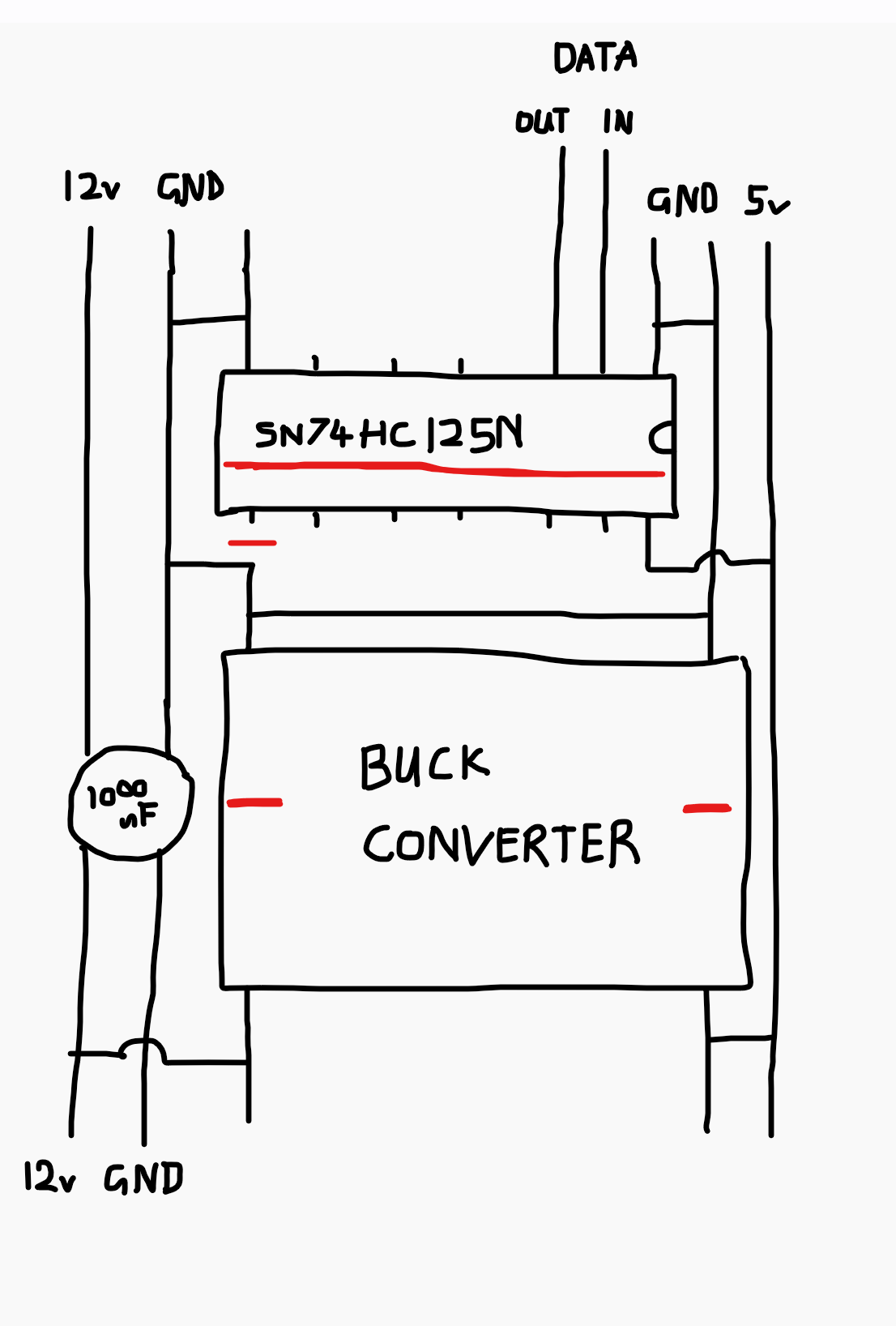
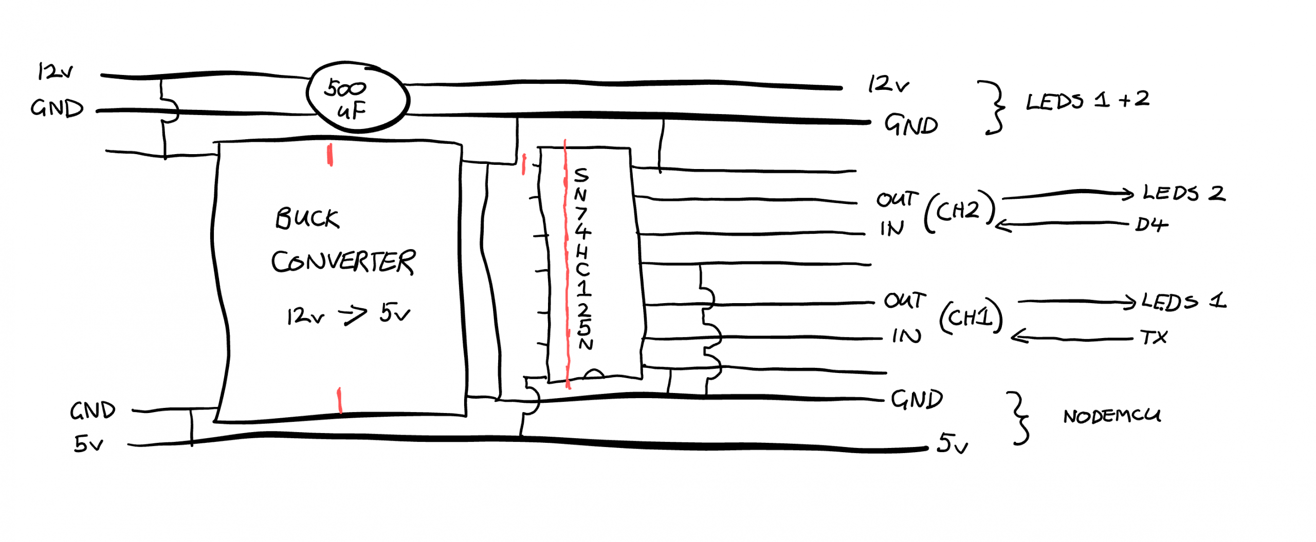
The new veroboard / circuit diagram
Initially we were only powering one light strand per NodeMCU board, but we’ve proven we can do two strands per board (this is apparently the recommended limit). Each SN74HC125N is able to bump 4 signals up from 3.3v to 5v according to the datasheet, so the cleanest way would be to have a single power source, and a single SN74HC125N to power one NodeMCU board with two strands.
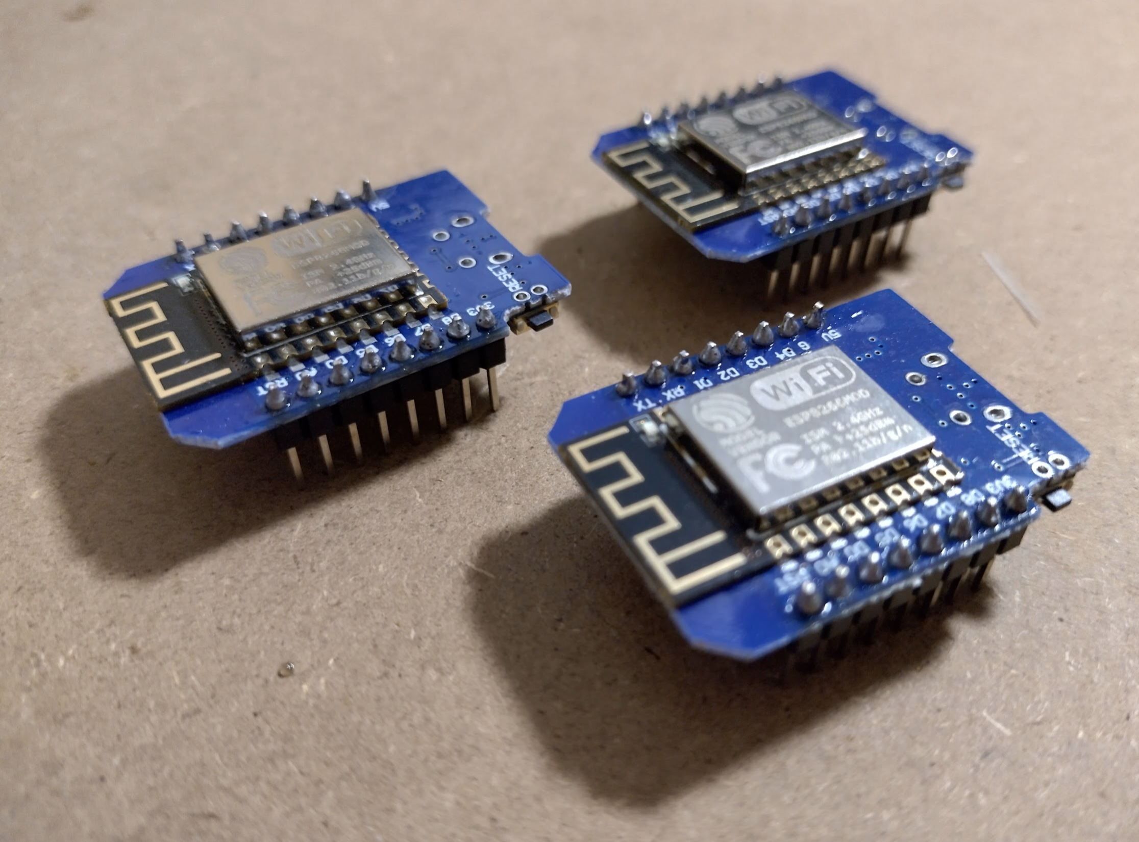
I also now have some much smaller (and cheaper) nodeMCU ESP8266 variants known as Mini D1 or WeMos Lua that I’ll see if I can shift this whole circuit over to, so it should look something like this.
Testing the new board
Initially the mini D1 powered up, but no lights. If I bypassed the level shifter entirely I could get the lights to work. After testing I discovered the buck converter was variable and set to 10v!! Surprisingly nothing released its magic smoke. An adjustment down to about 5.1v later and everything came to life.
It all looks great with the NodeMCU mini D1 variant, we have our controller circuit good enough for “production”. I believe I have enough parts to make 5 complete controllers controlling 10 strings of lights. If I split the test led strand in to 5 leds each I can do a proper scale test of it all. After that it’s over to working out where the controllers can physically sit, getting xlights configured, and lots and lots of 12v supply.
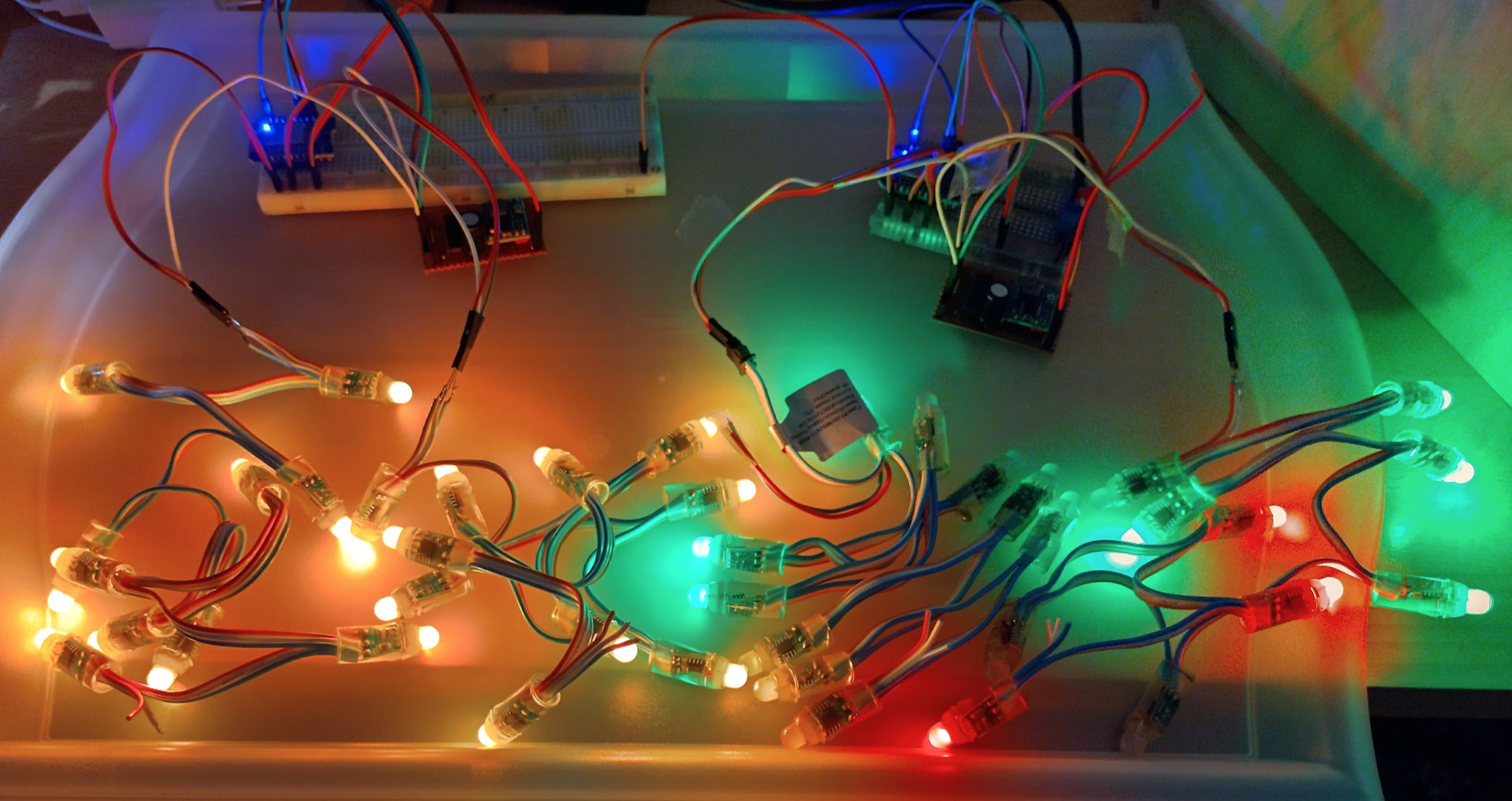
Minimum scale test
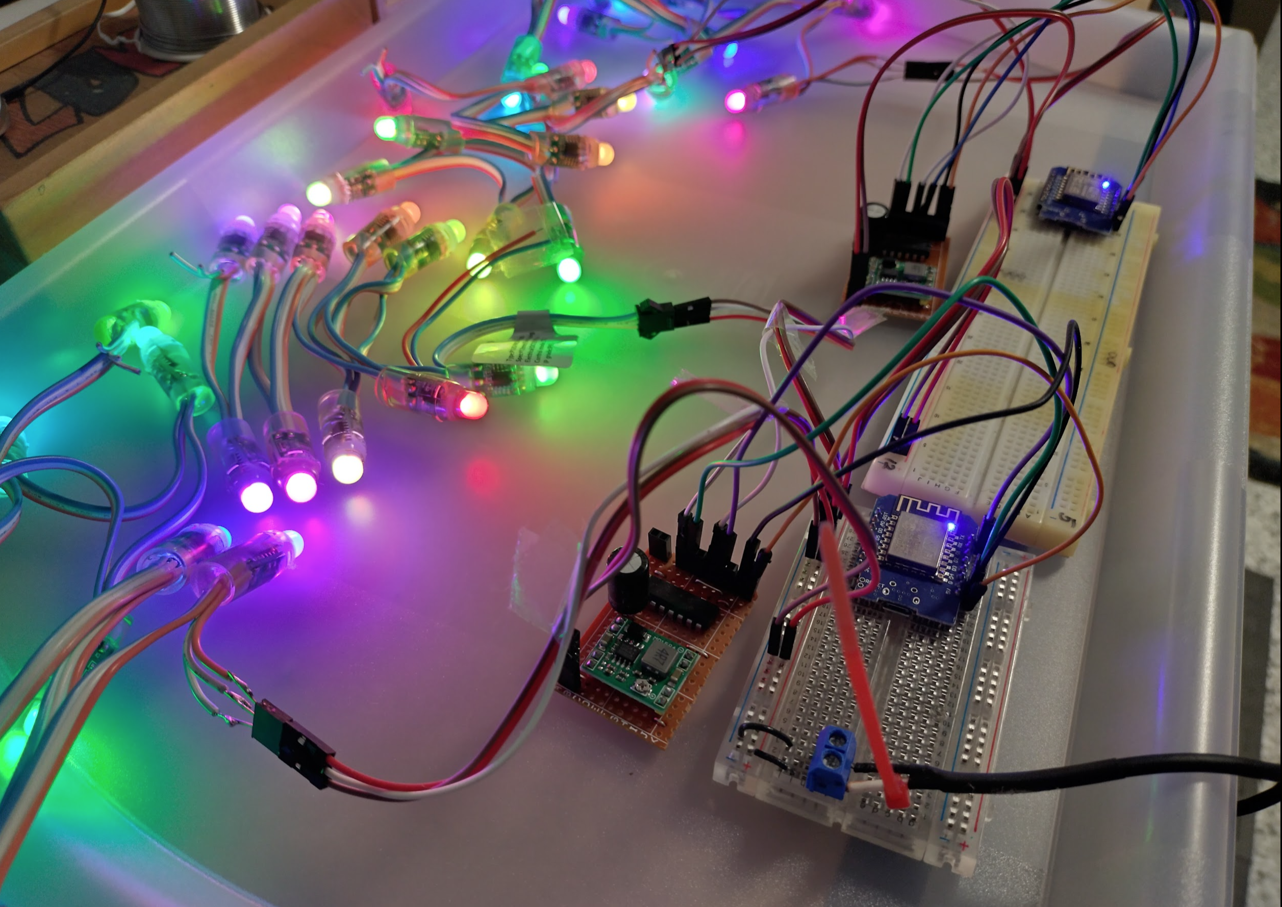
I decided to start with the minimum to work out xlights, which is only two boards. I have made a second custom power/shift board so I now have enough (2 power/shift boards, 2 mini nodeMCU controllers) to test xlights with this arrangement.
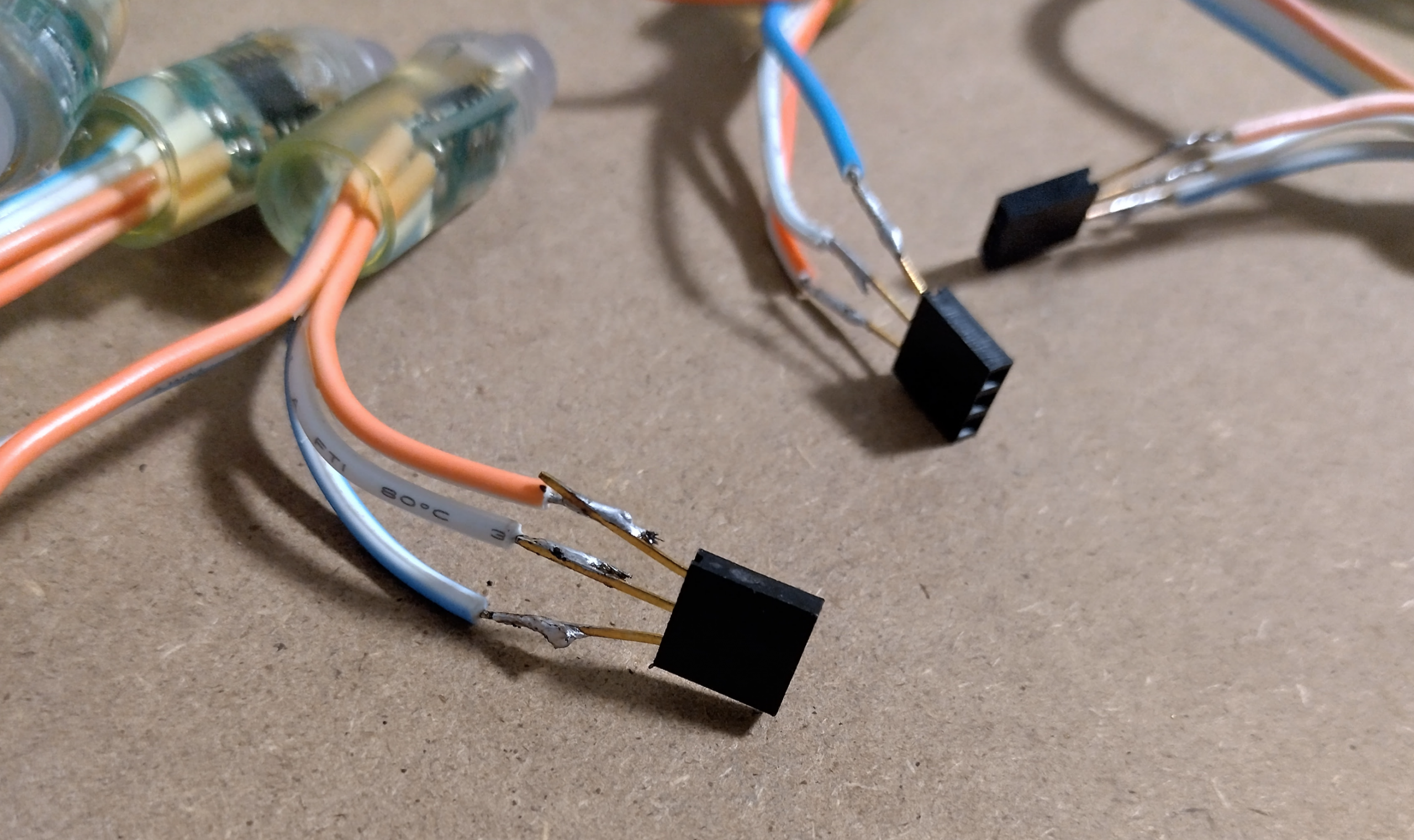
The led string I have split in to 4 strands of 10 leds each. This leaves 2×5 LED spare strands for the later test (when I solder 3 more of these shift boards), along with the ability to split these new 10 led strands in half later. The 4x10led strands have been quickly soldered so a tiny socket to allow for quick testing. Remember, the signal wire (white in this case) will only work from one end. So if your lights have power but aren’t lighting up, you might be sending the signal at the wrong end.
After wiring it all up, a manual WLED test was successful showing there’s now two independent boards with two strands each, making 4 separate strands to be brought into xlights to see if I can combine them all to be used as one scene, but also to be used individually if the xlights timeline entry wants to.
With the current equipment of 4 strands, if it scales to full “production” testing it will allow for only 200 lights according to the recommended limits. These pixel strands tend to only leave 10cm between lights if that, allowing for only 20m which is about the length of a common garden hose and not enough for a half-decent house outline. With the plan to create another 3 (bringing the total to 5 controllers) it should allow for 500 lights at 50m length which should be ok.
The tricky part will be how to arrange an outline of 10m lengths, with the controller sitting roughly in the middle of each & getting decent 12v to them. But that can be organised once the xlights step is done.
xLights initial trial
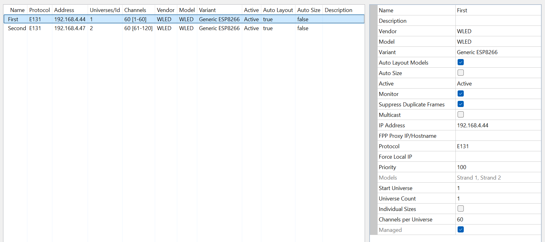
Just incase you’re jumping directly to this point, some important notes (tailored to this board configuration) are:
- Each nodemcu will be one unique universe (this ISN’T just for multicast!! I have written a note down a bit explaining this.)
- Each led consists of 3 channels (RGB). So for this trial I have two strands of 10 leds each, so each board will be assigned 60 channels. Note: Channels start at #1 and not #0.
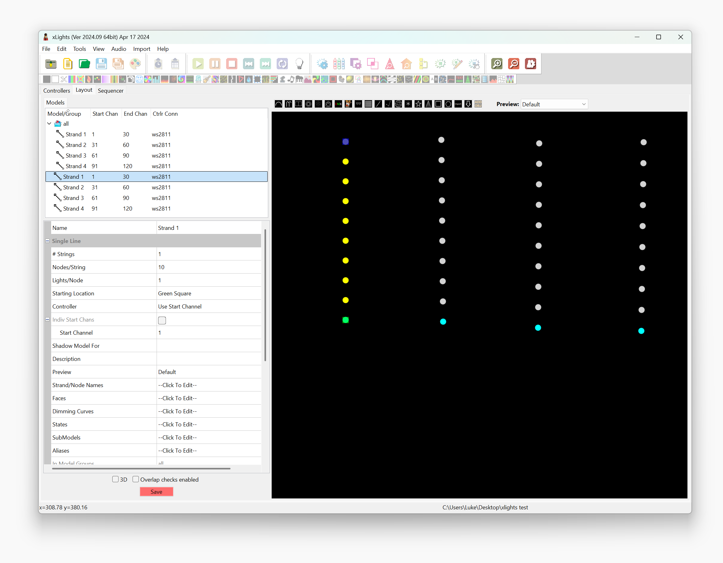
- In the Model/Layout, set the strand or led string controller to “Use Start Channel”, as it looks like it’ll be easier to work by channel number rather than by universe.
- To have an effect span across the whole house, create a group, set the “default layout mode” to “Minimal Grid”, add the led strands to the group, then add it to the timeline.
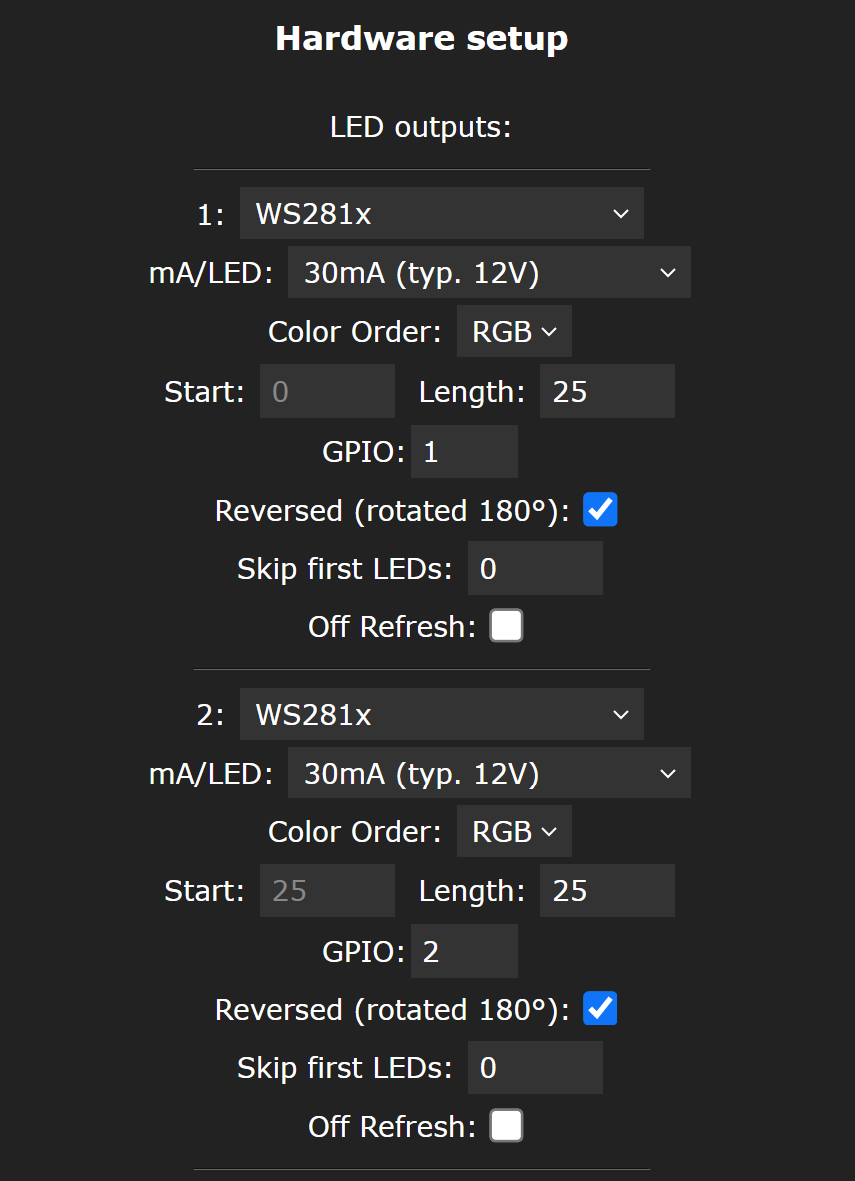
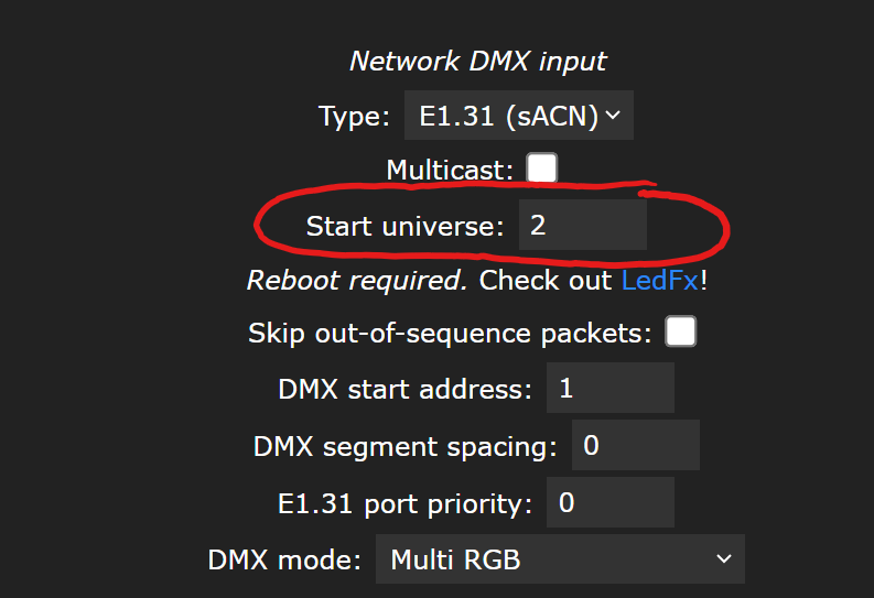
This configuration (for nodeMCU’s) needs the following settings:
The goal is to see if the controllers can relay the xlights show, so I have chosen a simple pinwheel effect by dragging it to the “all” group, and setting the entire show to 10s and 50ms timing.
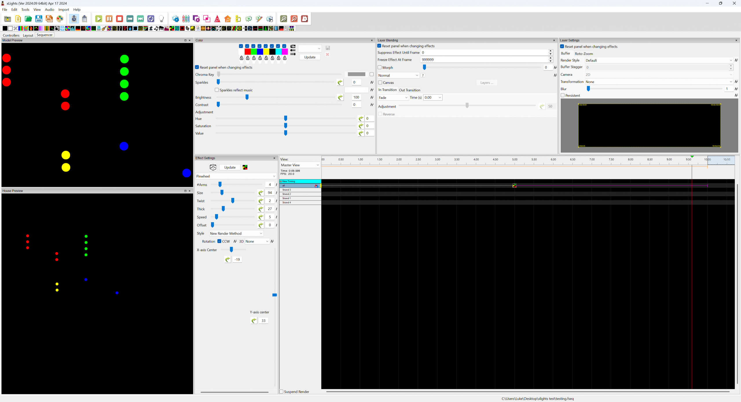
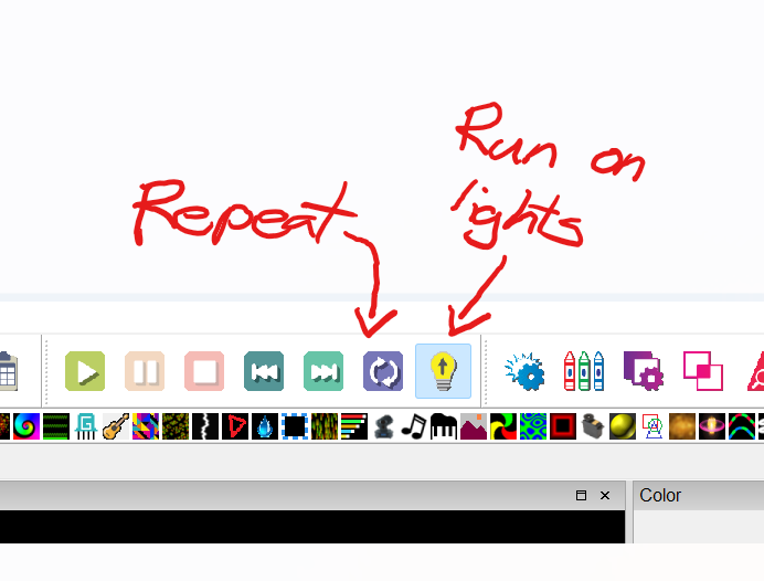
After working out which buttons need pressing, I had my sequence running on one controller but not the other. The second one appears to be having wifi connectivity issues everywhere other than the original test bench.
To try and resolve the second’s issues I have tried flashing another nodeMCU and even swapping it to the first switch/shift board’s power but I just can’t get a second one online consistently which is a bit odd as it worked flawlessly on the initial test bench. So for now I believe the xlights part of this is working well enough, it’s back to figuring out how to get some hardware to work.
Success!
I soldered all the other boards I had, reflashed them all to the latest stable wled, where I discovered the old one that wasn’t stable got red hot. So I have swapped it out one of the new ones and got halfway there with a stable wifi, and xlights could find it, but it wasn’t showing any pattern. The issue is you need to set the universe within the sync settings in wled.
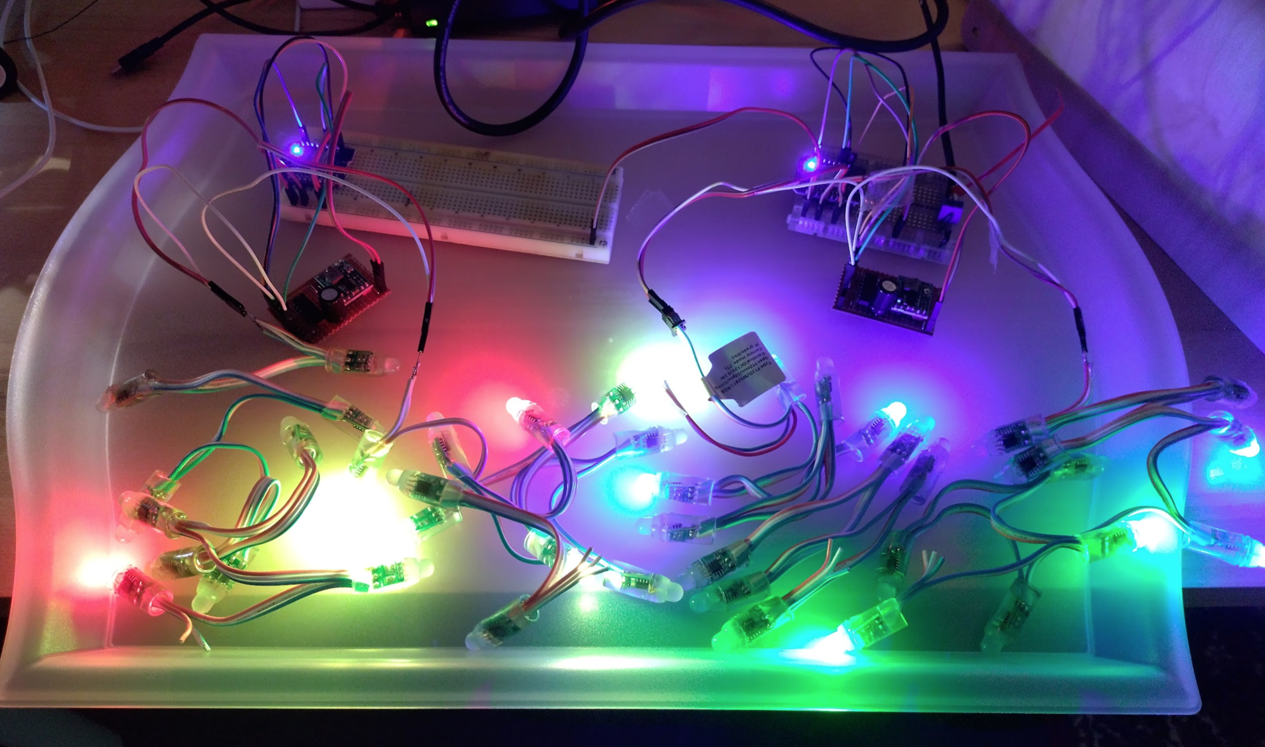
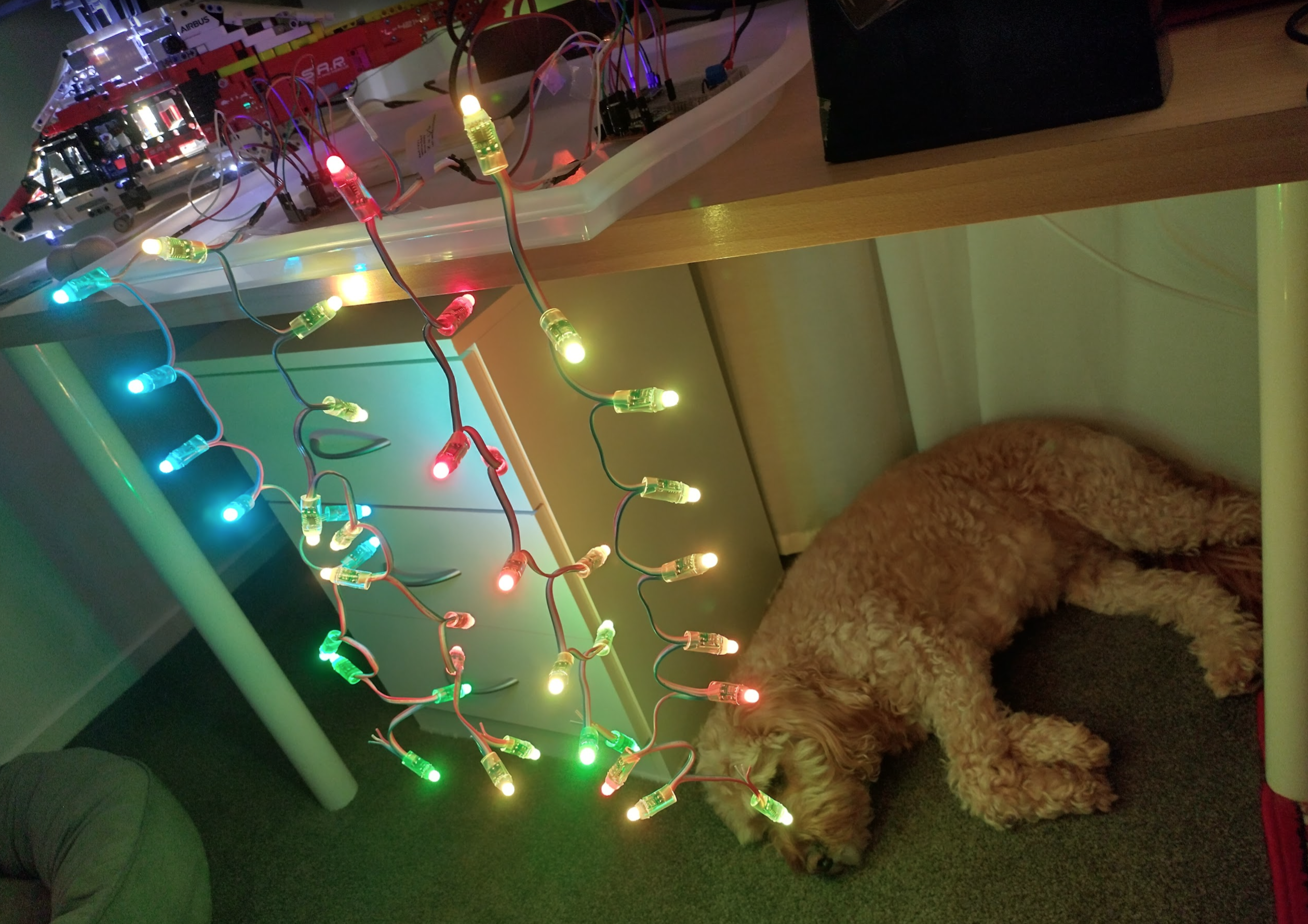
I rearranged the leds to just hang as straight strands. Not much can be done to display patterns and such but it’s a proof of concept for now, with patterns on the leds matching what xlights says they’d be.
So next step would be to make the remaining boards as they seem to be working ok, sourcing another nodemcu mini or similar, and then getting many many more leds.
Going a bit easier from here
I have decided to go a little more modular/off the shelf way and not tinker with circuits and such for this project as there’s so much more to it that can go wrong! So the custom wled modules and power supplies will be replaced with off the shelf esp32 wled devices making it much simpler to achieve in time. Follow the new journey here!