
I was testing an Arduino ATTiny85 based prototype device for just how far it could be pushed in capabilities. The initial idea was to see if it could be expanded with a common shift register to control more digital outputs, with the outputs specified by a website CMS. This was to test a web-connected christmas light theory. I got 8 leds working from two pins fairly easily, but a good christmas light display doesn’t have just 8 channels, so I tried a few shift registers linked together.
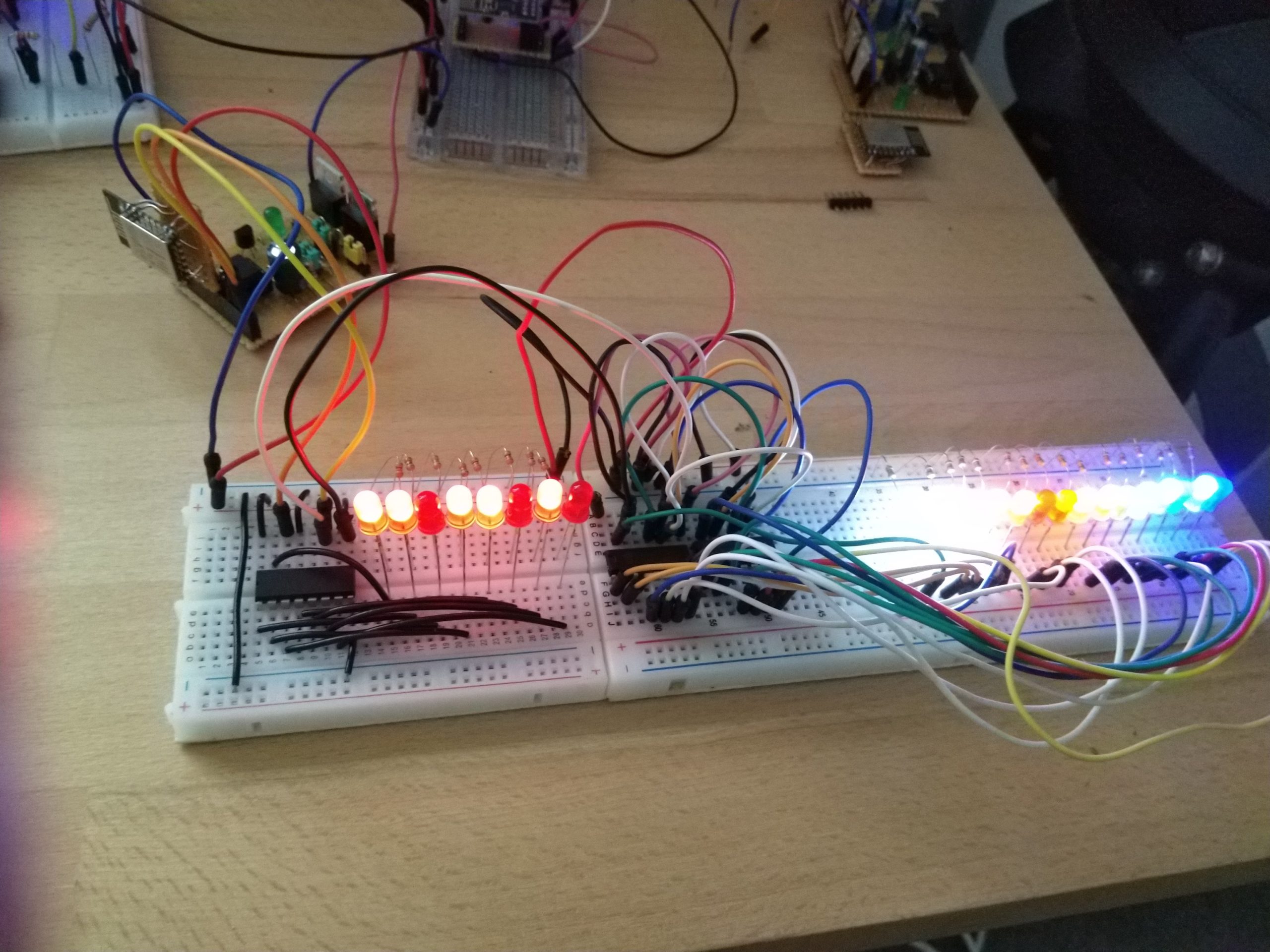
Problem was I only had two spare pins. This was good for switching leds but it would make them flick during updates. Good enough for now but I would have to solve it later. To test it I made the website have a number or character, and then the ATTiny85 based device would show the ASCII binary representation of that character on the leds. That way I could confirm the correct leds were being lit – proving the internet -> led chain worked. Once I realised I was displaying numbers/characters it reminded me of something I saw a long time ago…
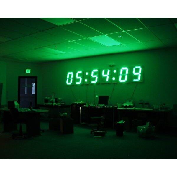
This is a giant clock that was made by a sparkfun employee way back in 2006. I remember seeing it not long after it was made and thinking that’s slightly crazy, but amazing. Back then I didn’t know how to create such a beast, Arduino was barely heard of, and GPS (which was used for the clock) was expensive. So to the back of my mind it went.
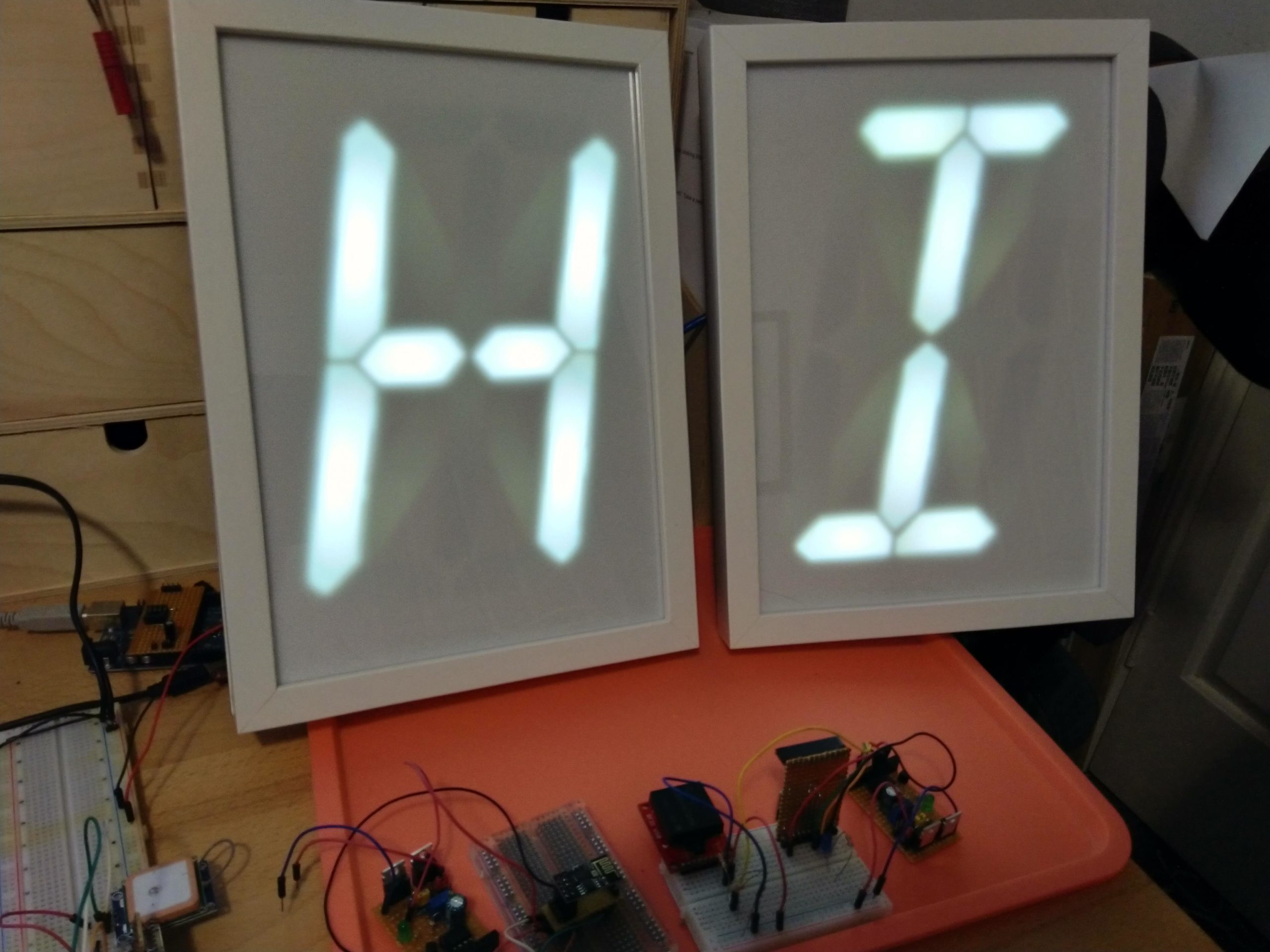
Here we are though with Arduino plentiful, and cheap wifi that would allow fetching of the time from an internet server. I was already showing binary as individual leds, why couldn’t I order those leds in to actual digits we can understand? So I went to work.
Digit voltage theory test
I was originally planning 7 segment digits to display numbers only. These are what you would normally see on a digital clock. Then it dawned on me that it wasn’t much extra effort to link two shift registers together to allow for 16 segment digits which would allow for uppercase, lowercase, and symbols to be drawn – this style is commonly seen on cash registers. With this decided I purchased the bits for a test.
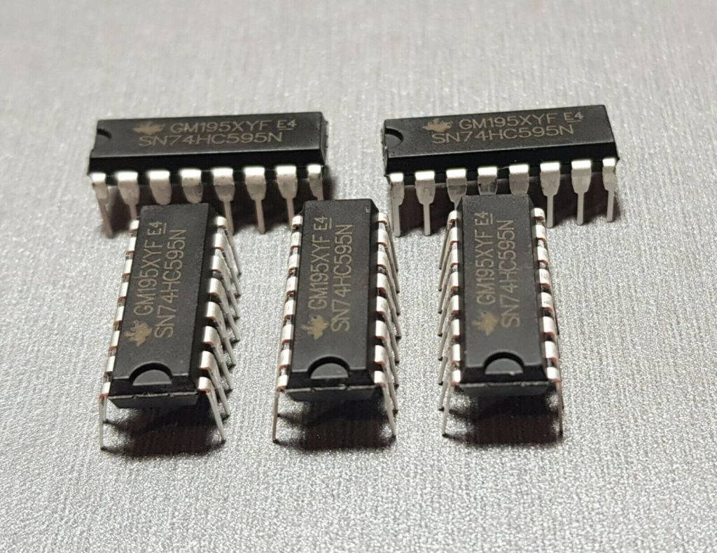
The brains behind each digit – shift registers. I wanted everything based around common components for reasons beyond this project. So these are SN74CH595’s. They’re used almost everywhere Arduino is, allows 5v with 3.3v switching (more on this later), 8 outputs, can be daisy chained, separate latch/clock/data, etc.
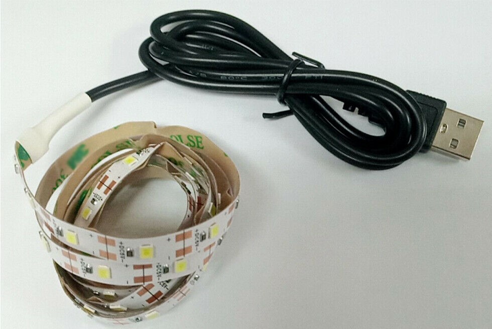
The led strip. I started out with a 12v led strip for a different idea but figured if I could use a 5v led strip which are usually powered from USB, I could easily power it from what I am using. I went with cool white as then I could change the colour later using a coloured perspex or even cellophane if needed. I worked out up to 50 leds per digit, and given I ordered 10 shift registers and I had two already, lets go for 6 digits. A 300 led strip is perfect.
Once these arrived I went to work designing a small double shift register board to control a single 16 segment digit, as I wanted these digits to be perfectly standalone should I want to reuse them for something down the track, or make more.
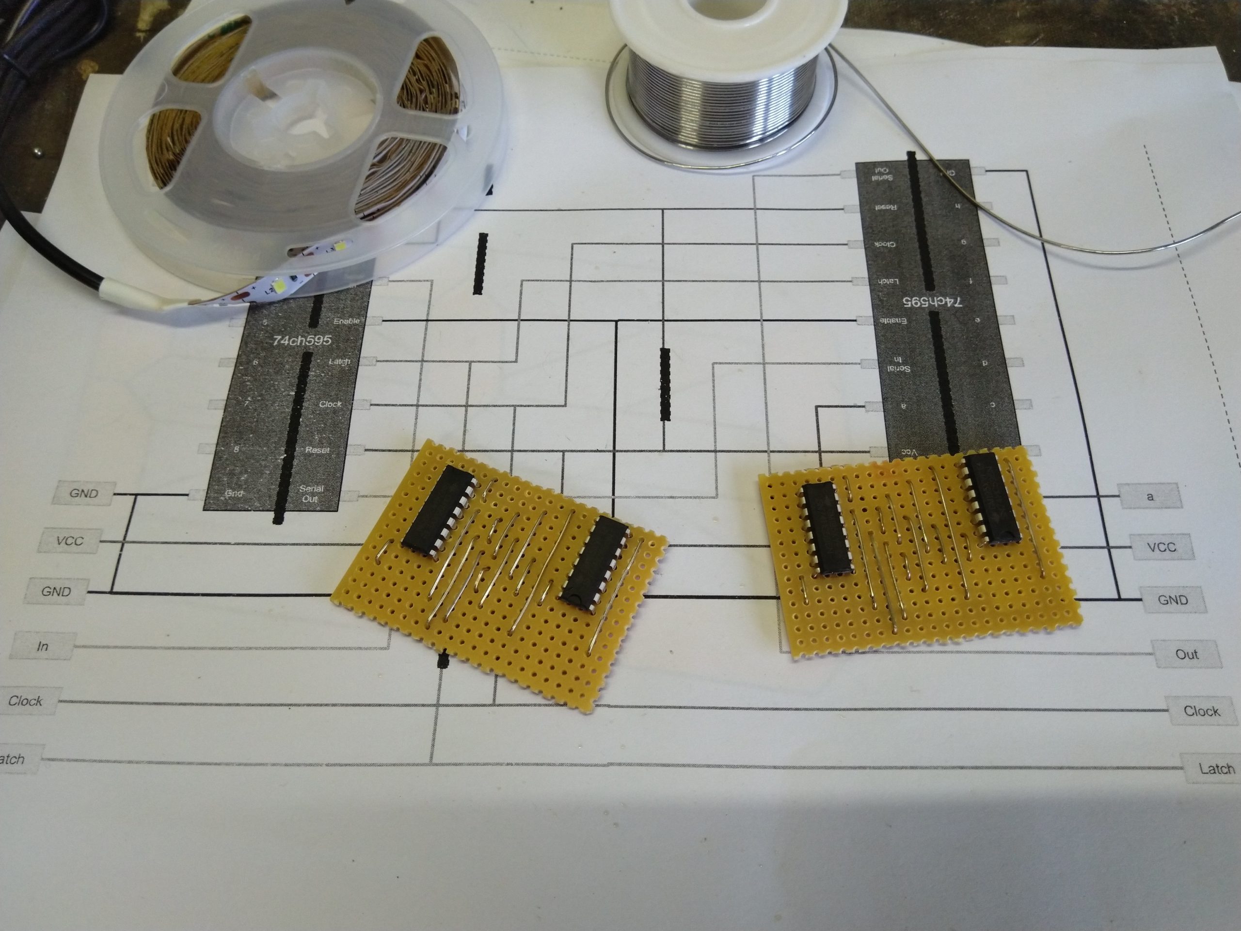
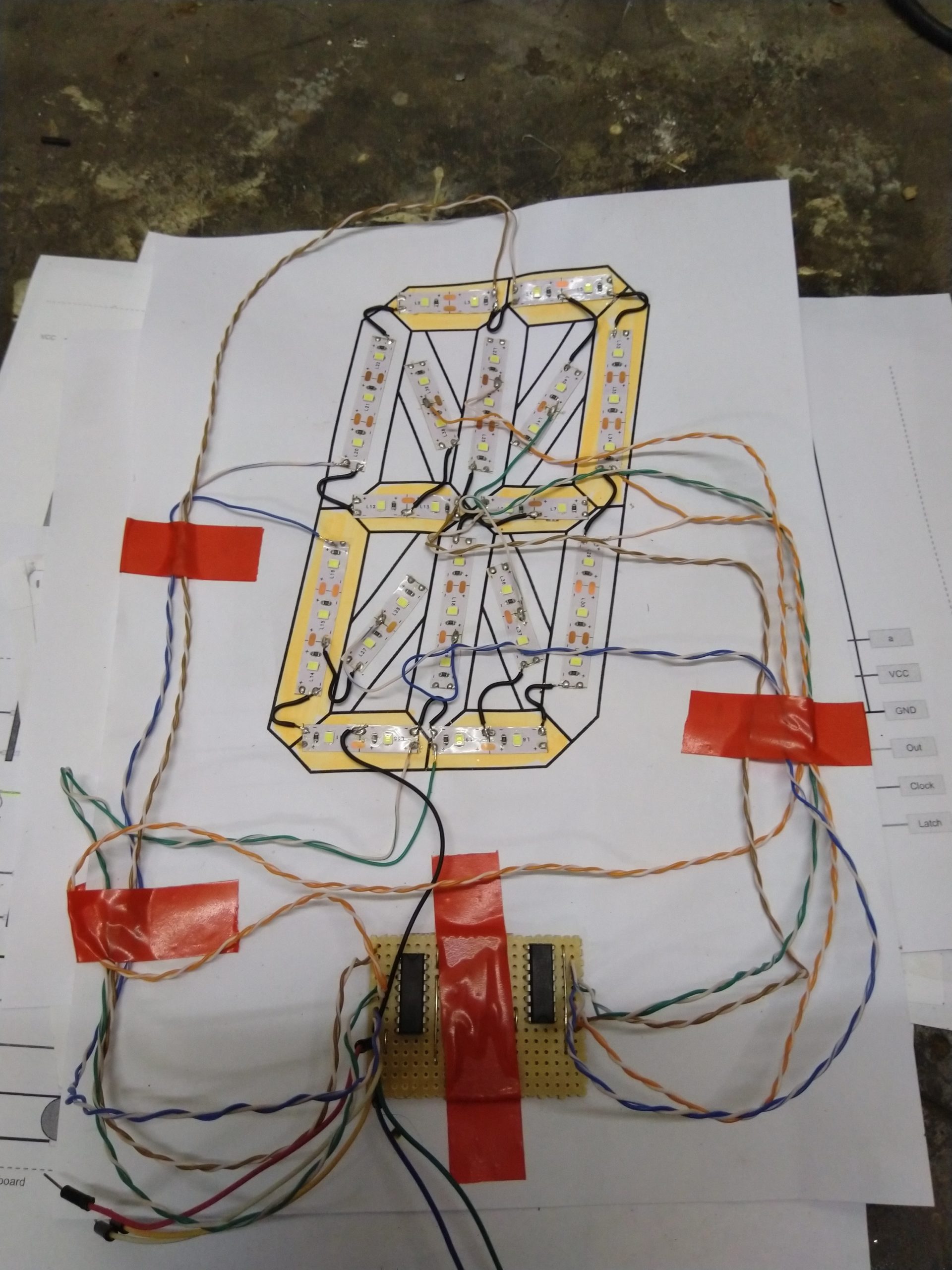
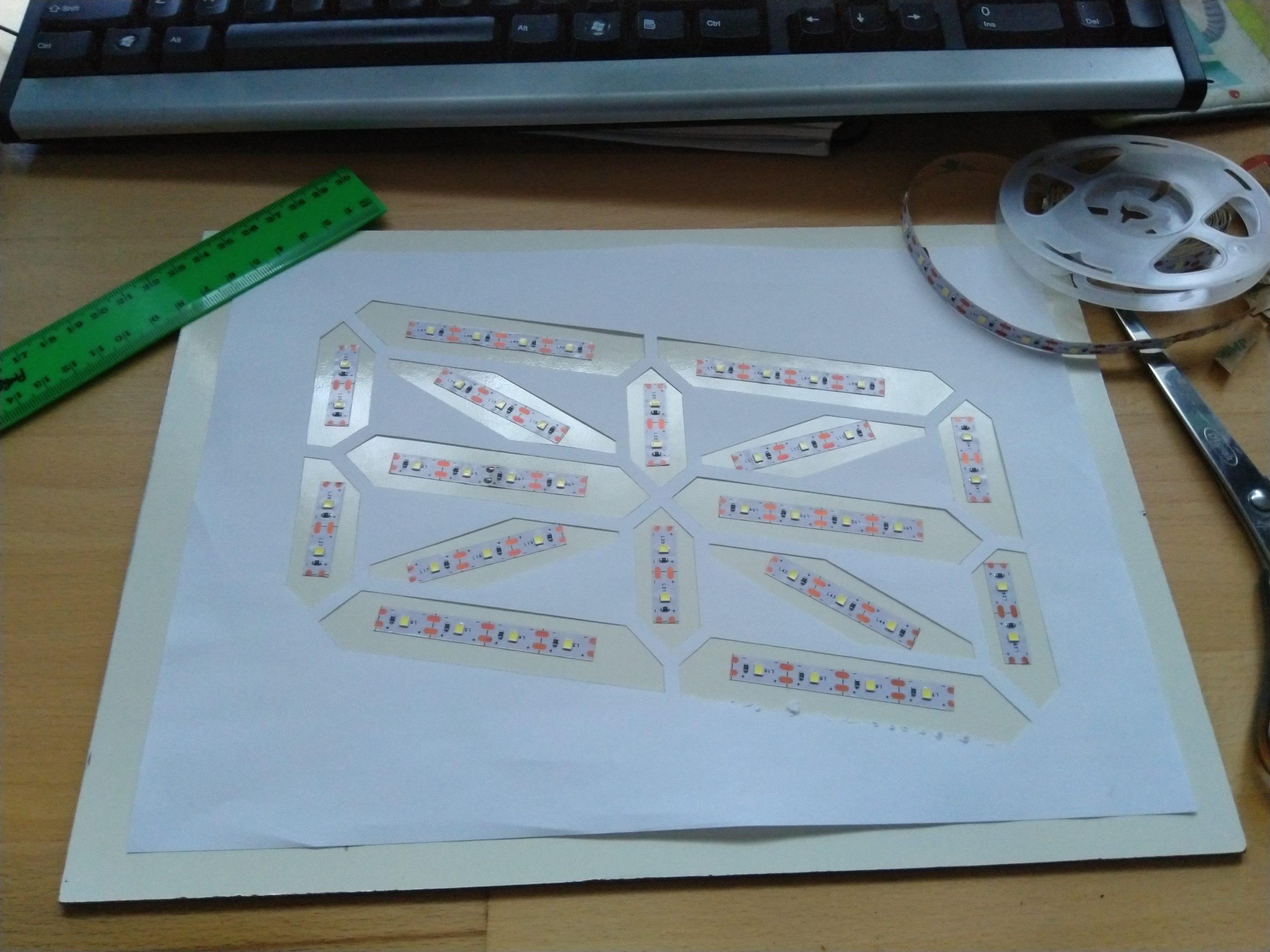
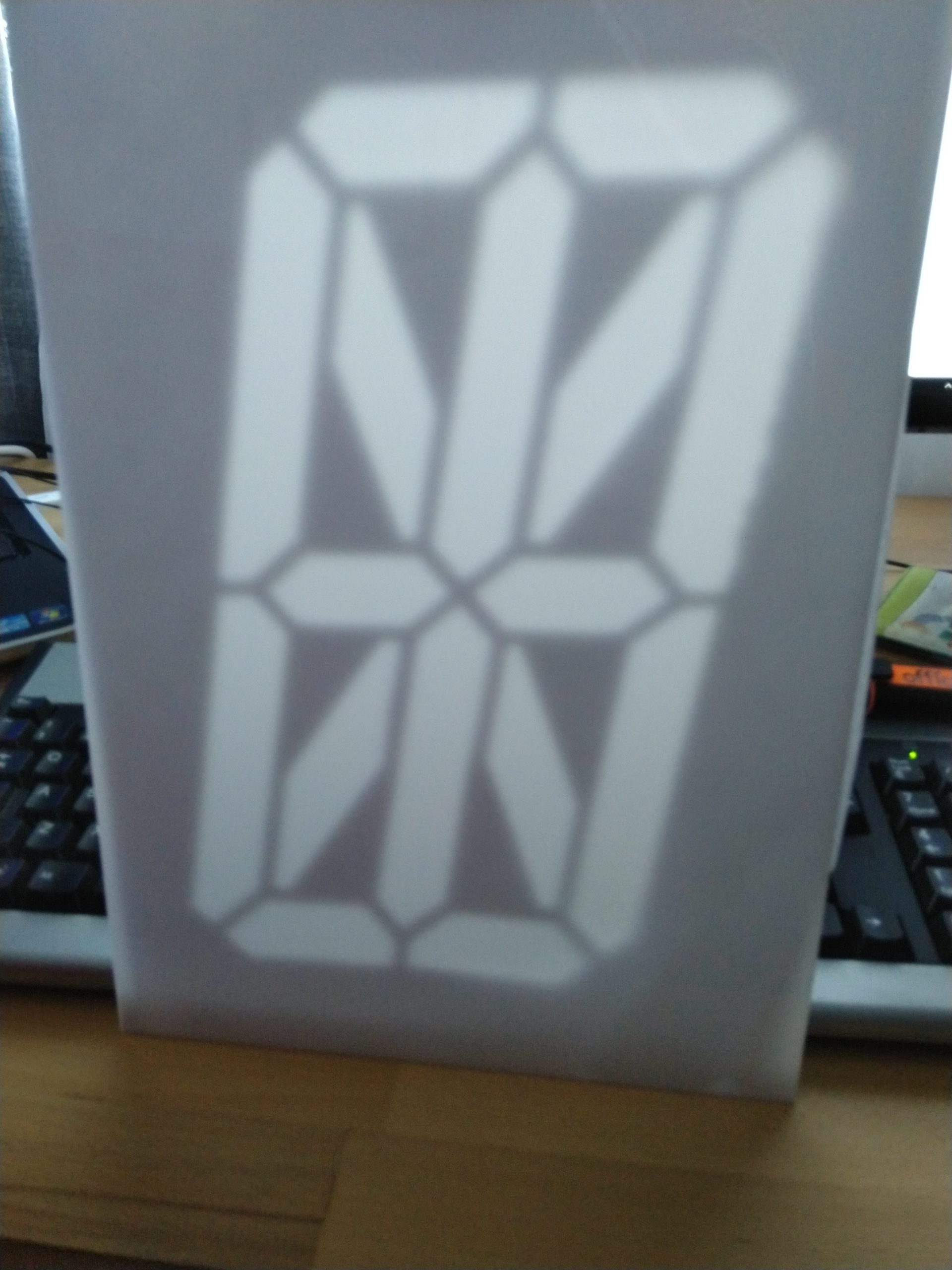
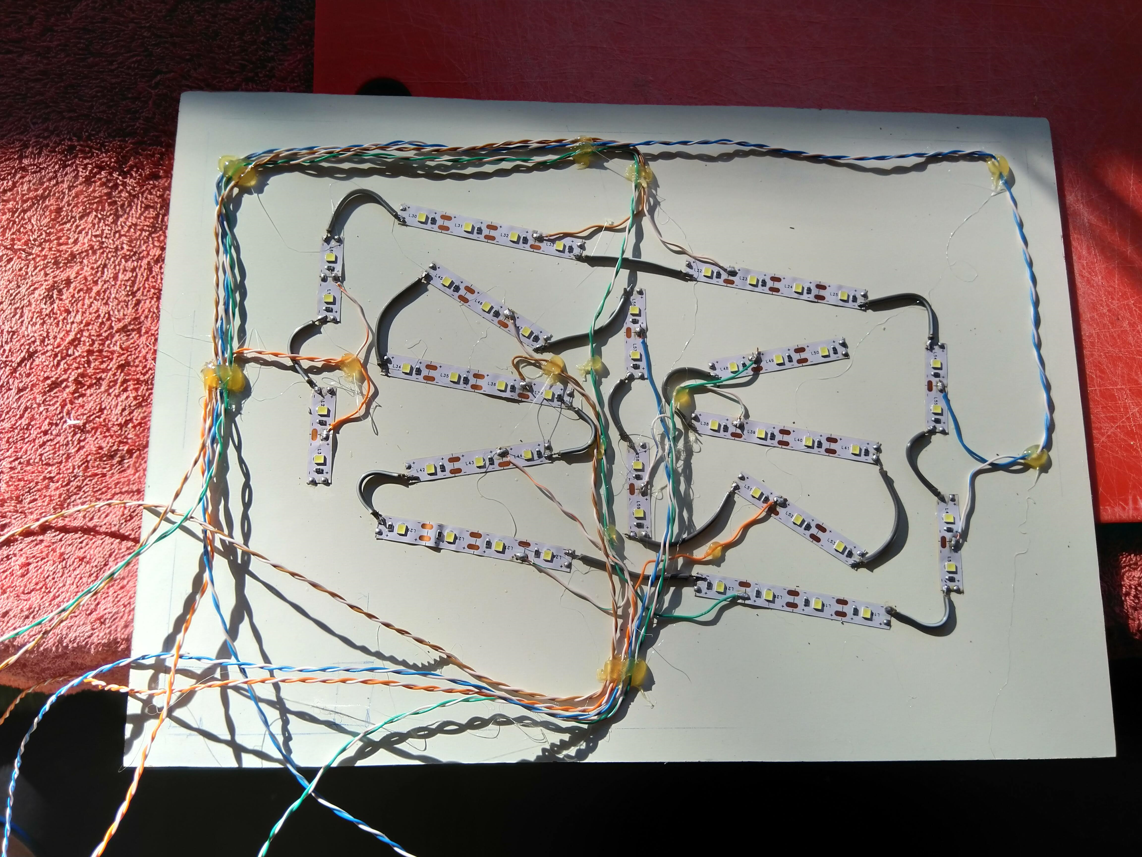
With a board done I can try powering the led strips through them with a mock digit to prove the theory. I made up a template and got to work with the fiddly soldering, choosing ethernet cable to do the job. All of this attached to an A4 sheet of paper I powered it up.
This showed the shift registers and boards and internet connectivity were all good. It might actually work! Time to go all in and get serious about this.
Purchasing all the goodies
I had to find an appropriate box or frame to come up with the end size before I could go any further. The requirements were:
- It had to be deep enough to allow the led strip light to disperse enough giving the appearance of a fully lit segment
- The blocking material between the segments needed to be tightly packed and relatively easy to work with
- It had to accommodate a diffusion layer
- It had to give a relatively professional appearance to look close enough to what a giant 7 segment component would appear.
- It had to look extreme, yet tasteful! To go to this much effort I didn’t want to end up with tiny displays.
I ruled out making my own frames early on due to the work involved. This pointed me in the direction of deep photo frames as these would have the depth for the light dispersion. Ebay seemed to have some but they were expensive and in the wrong size. Eventually IKEA came to the answer with these:

IKEA “Ribba” photo frames. These are a white plain finish, thin glossy perspex front, 1 inch depth, and can fit an a4 sheet. All I would need to do is provide a new backboard that can be screwed to the frame. Now that the size and depth are decided, on to what will be the blocking material.
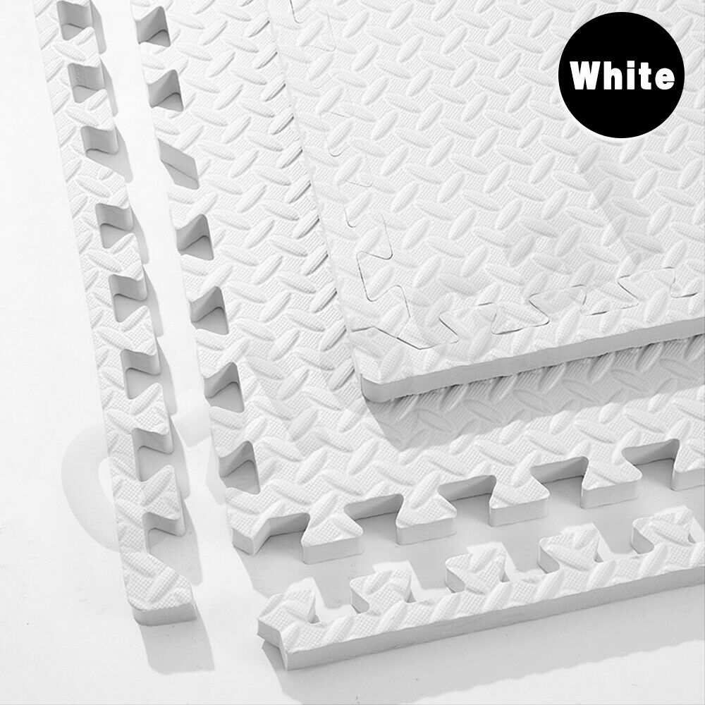
Locking foam matting. I knew it was possible to make tight clean cuts with a stanley knife after working with this previously. This would allow around 5mm between the digit segments. Also it’s the perfect thickness of around 1/2 an inch, meaning two squished together would fit in the frame. Each mat can contain 4 A4 sheets, meaning I can get 2 complete segments from one mat. I chose white to allow the light from the leds to bounce around and disperse a little more. The concern was that I would lose the dark appearance of each segment when the leds weren’t lit but this worked well. Now to find how to disperse the individual leds.
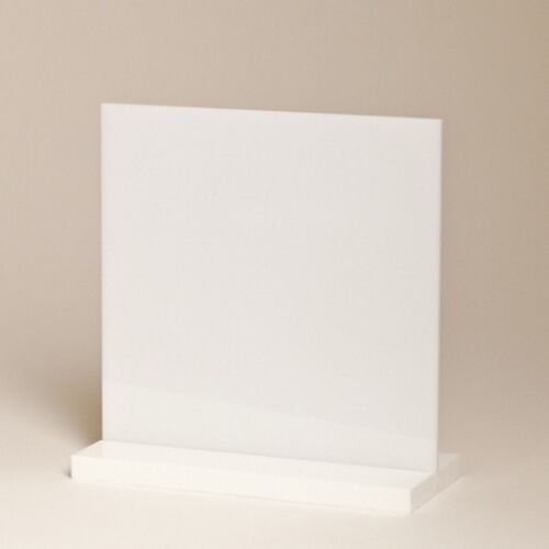
White “Opal” Acrylic/Perspex. This is used in light up signs or anywhere that light needs to pass through but still have a solid appearance. It comes in a4 sizes which is perfect. I went with a trial of a single sheet at 2mm thickness to see if it would allow more light through and help make the individual digit segments a little clearer. This was the most expensive part of each digit.
I was running low on veroboard also so I decided to get some of that. This took a little longer to get which delayed things a bit.

Full size & wiring test
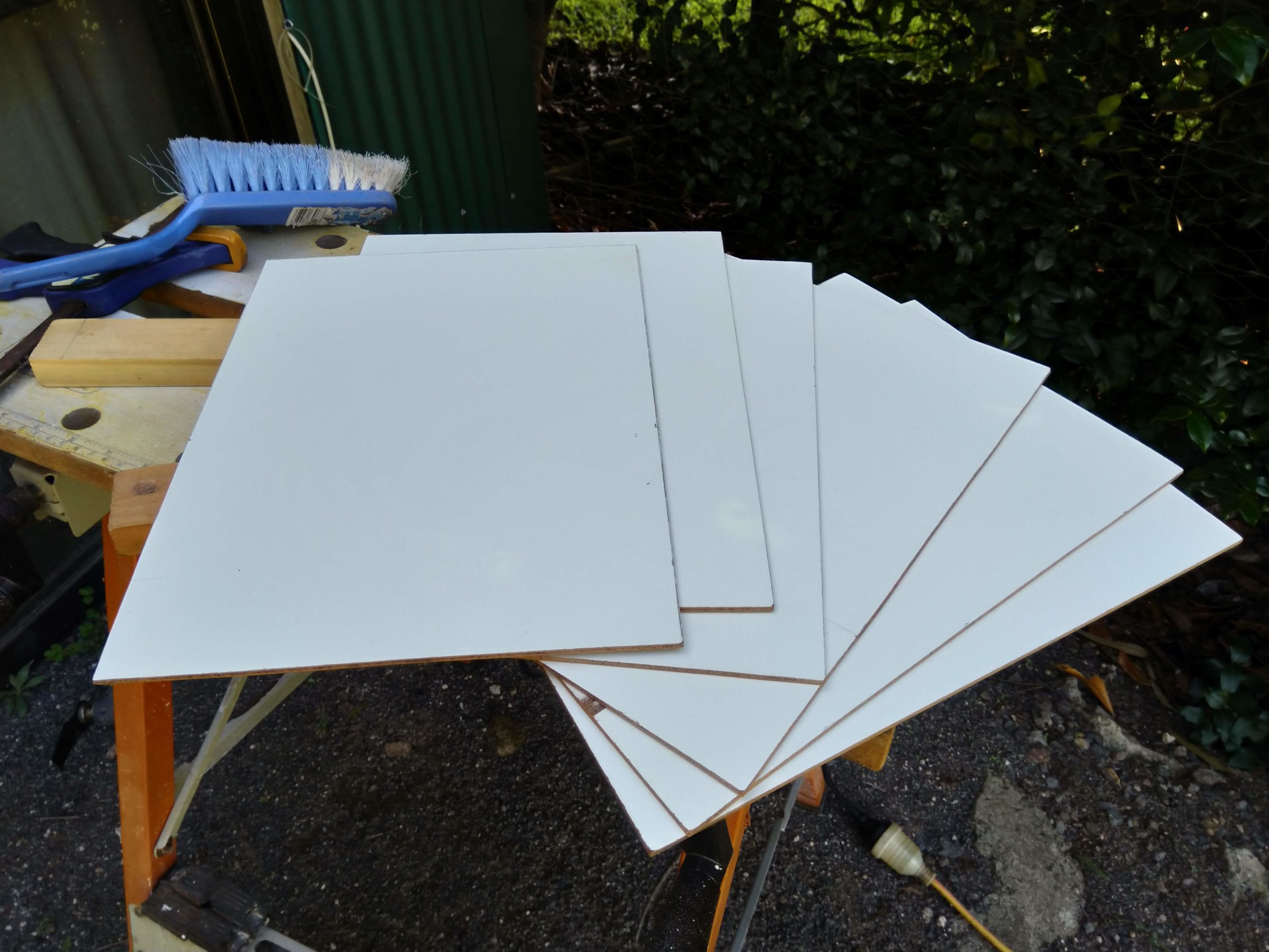
Now that all the parts were on their way and the size was decided, time to get working on the bits that I could until each piece arrived. The backboard material I had already which was a glossy white board to help the light bounce around inside each segment a bit more. I got started cutting these to match the outside size of each photo frame.
I went on a google search to see what a nice 16 segment display was arranged like. There were a few differences:
- The horizontal segments were sometimes only divided with a straight line, instead of the middle vertical segments eating into them. The middle vertical segment was then a square end only, rather than pointy.
- The diagonals might be more pointy which creates more of a defined star shape in the centre rather than a +.
The different designs seemed to be geared towards what the displays would be showing. The solid lines were geared towards regular 0-9 digits as a priority. The more pointy ends prioritised text (especially lowercase) as it can show angles better. I ended up going for a nice design halfway as I wanted an even mix of numbers, uppercase, and lowercase.

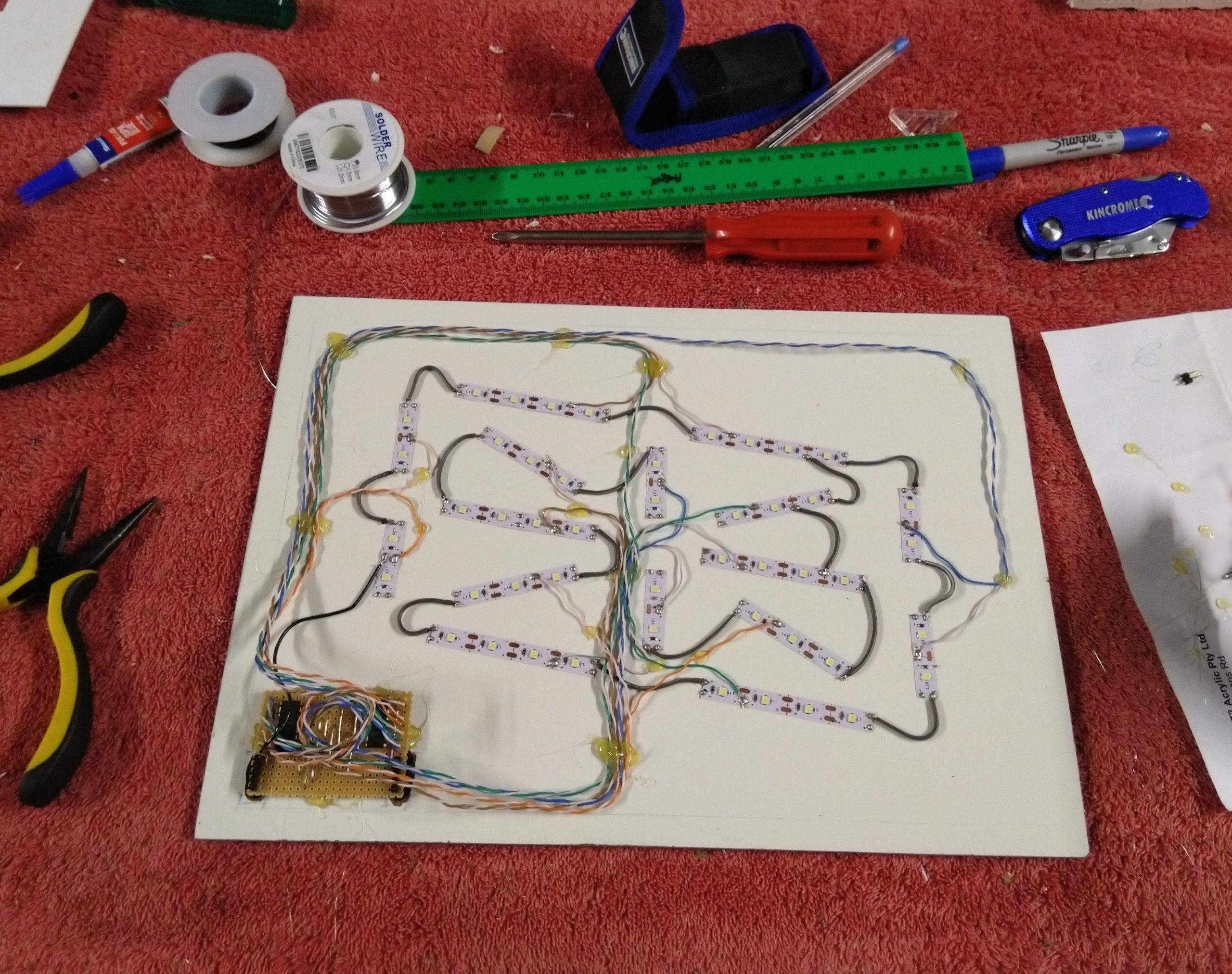
With all the leds stuck down to the backboards, it was over to doing the easiest option which was connecting all the grounds together en mass. Here I used leftover stranded wire which was a mistake. It is very thick and it didn’t need to be, also the stranding meant each end needed to be tinned. This took an enormous amount of time to cut each piece, tin it, solder it down. To save time use thin solid core wire like ethernet.


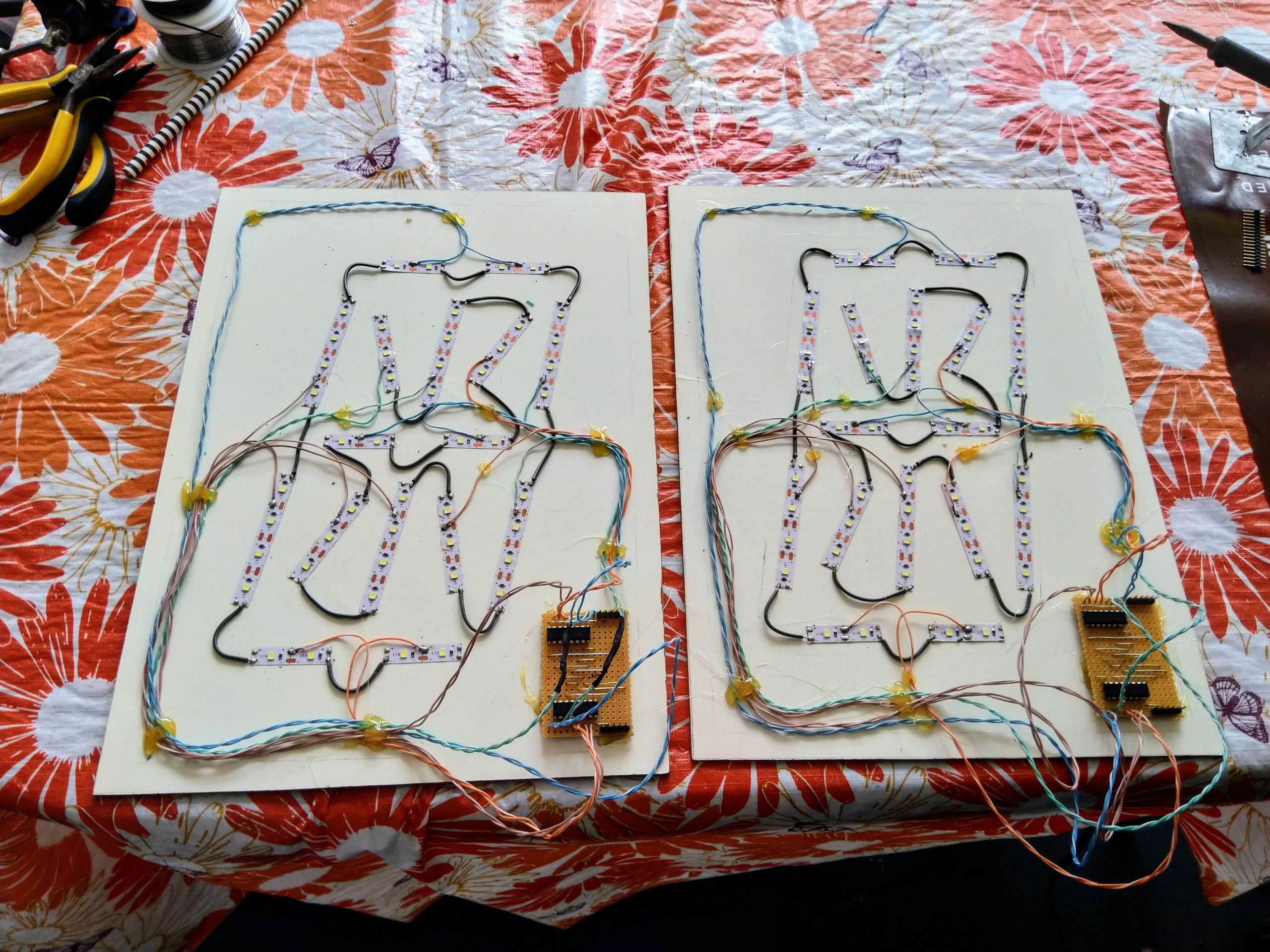
Then it was over to a more formal wiring layout than the paper test earlier. I used stranded ethernet here thinking the flexibility would be an advantage. The colour coding and 4 pairs that ethernet has made it easy to keep track of which wire went where. I even got two green pairs mixed up showing how crazy this is. I decided to start with just two, that would let me test the digits passing information to eachother.
I used hot melt glue to stick it all down, this occasionally came unstuck while waiting for more parts to arrive but superglue fixed that.
It was then on to see if this all worked still. I fashioned a jumper cable to join the two digit boards and gave it a go. This proved that the signal could pass from one board to the next. I was surprised my scrolling code worked first go! I had the issue of the led segments flicking still due to the floating latch, as I only had two pins to play with. But I had researched a solution and parts were on their way.
Fitting test
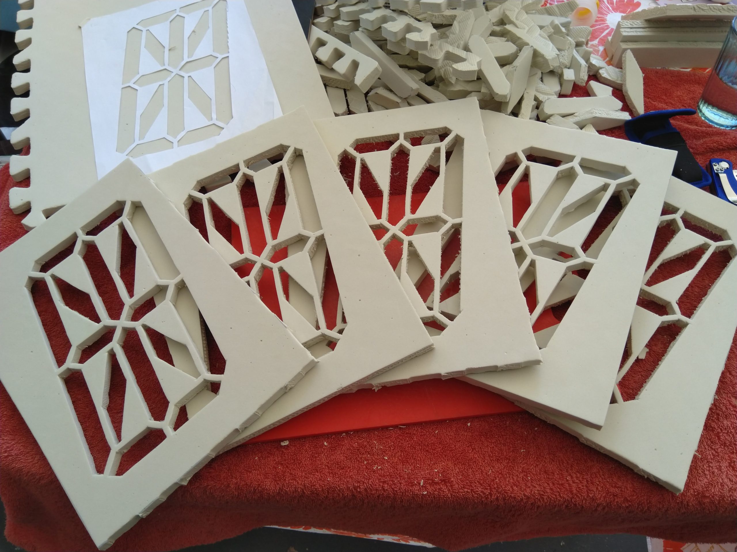
This is where the foam cutting begins. Lots of cutting. The foam had arrived and it isn’t as white as I had planned but it’s good enough to start with, the testing would show whether it’s ok. First was to mark out all the corners on to the foam once it was cut to A4 size.
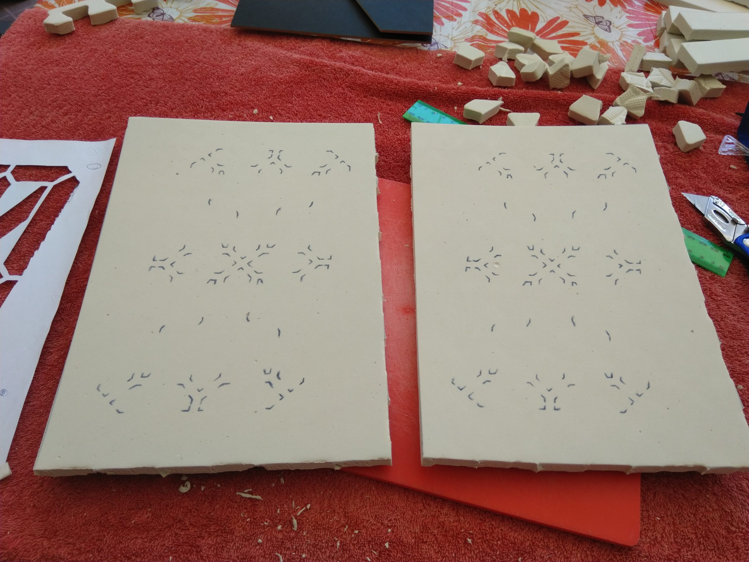
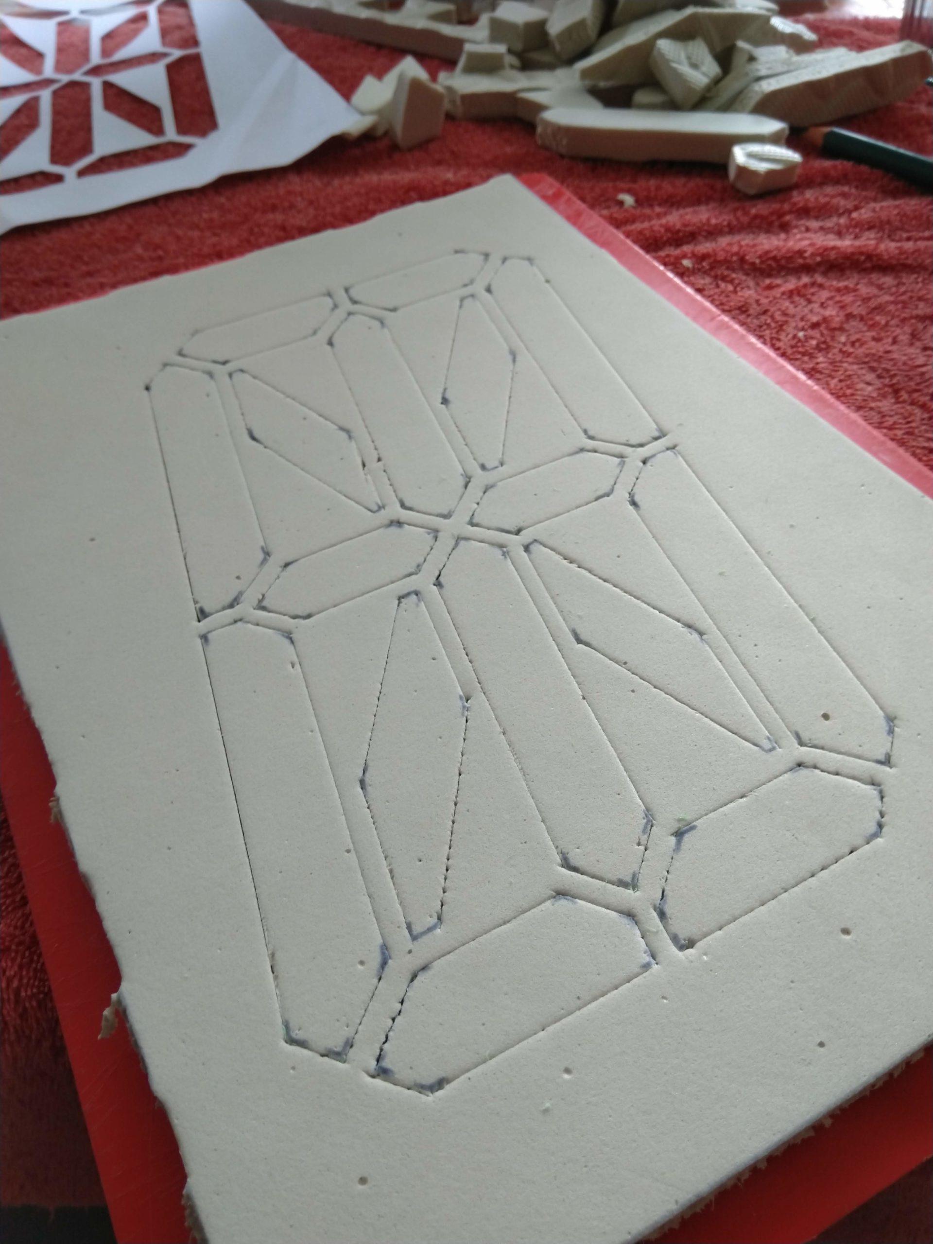
Then it’s over to the long slow process of cutting through so the segments could be pushed through cleanly while leaving the 5mm or so between them.
Here’s a few tips I discovered while doing this:
- Make sure you have a sharp stanley knife, and change the blade every 2 or so foam pieces. This prevents the foam from beading or dragging when the cuts are made as you can see on some of the digits.
- Use a ruler and press hard when making the cuts so that they go right through.
- Do all the cuts in the same direction in one go. I did all the verticals, then the horizontals, then diagonals on one side, then the other.
- Once done, do all the cuts again but only do 1cm or so, and from the opposite direction that it was cut initially. This gets the bit that is missed when holding the stanley knife on an angle.
- Flip the foam over, and use the stanley knife to cut any bits that are still stuck.
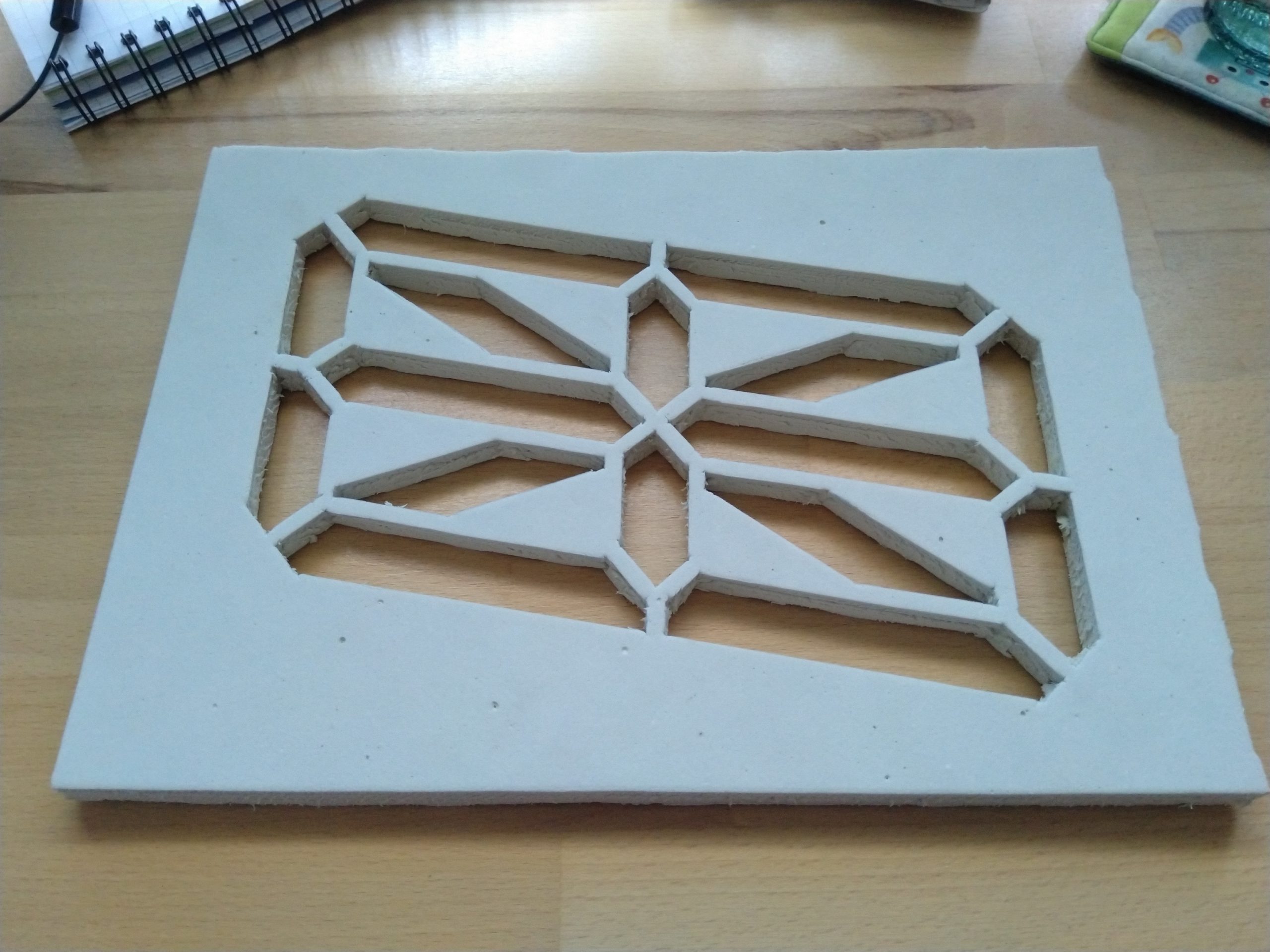
Once it looks ready, the pieces should pop out with a little bit of effort leaving you with a nice clean digit!
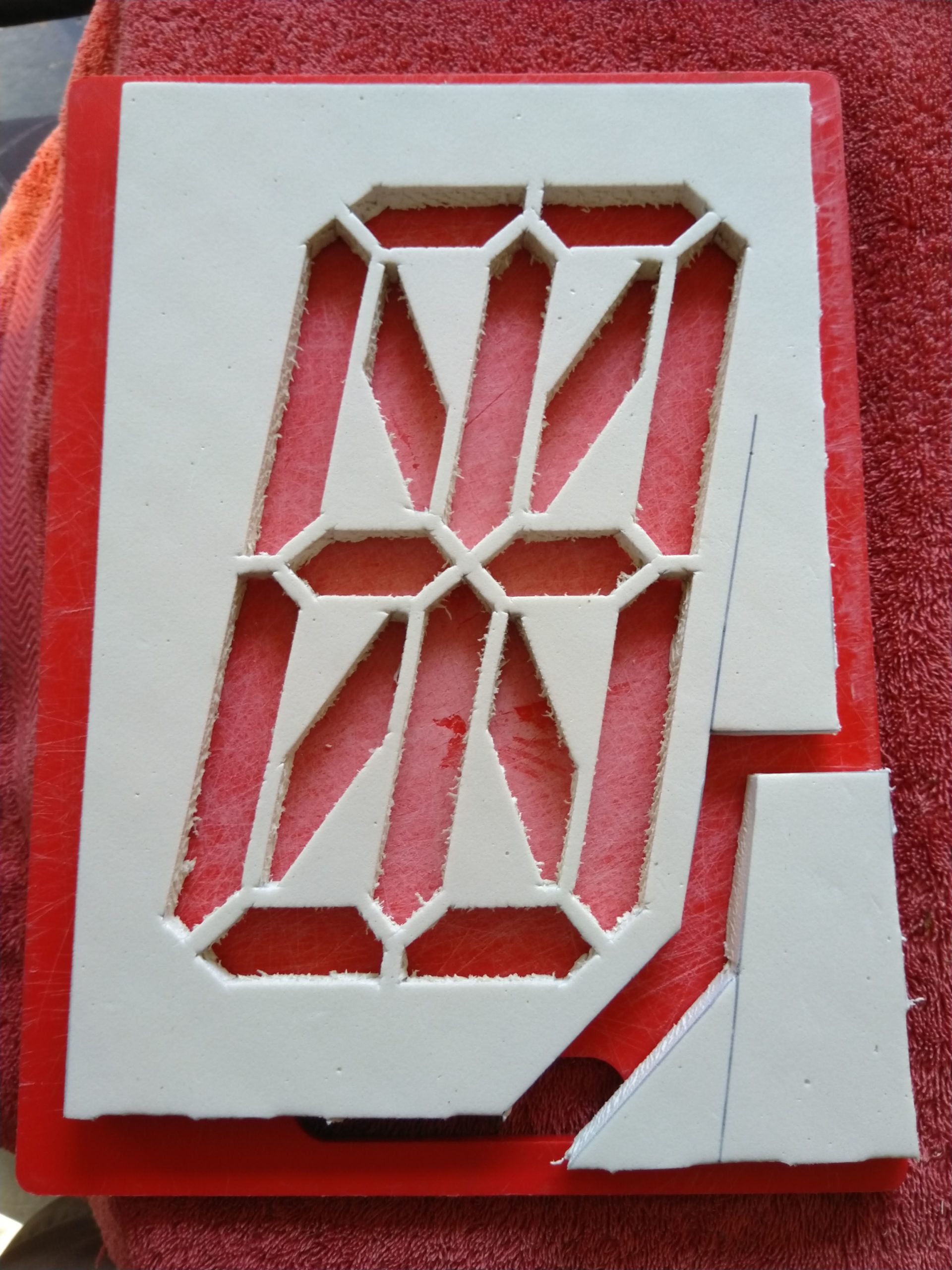
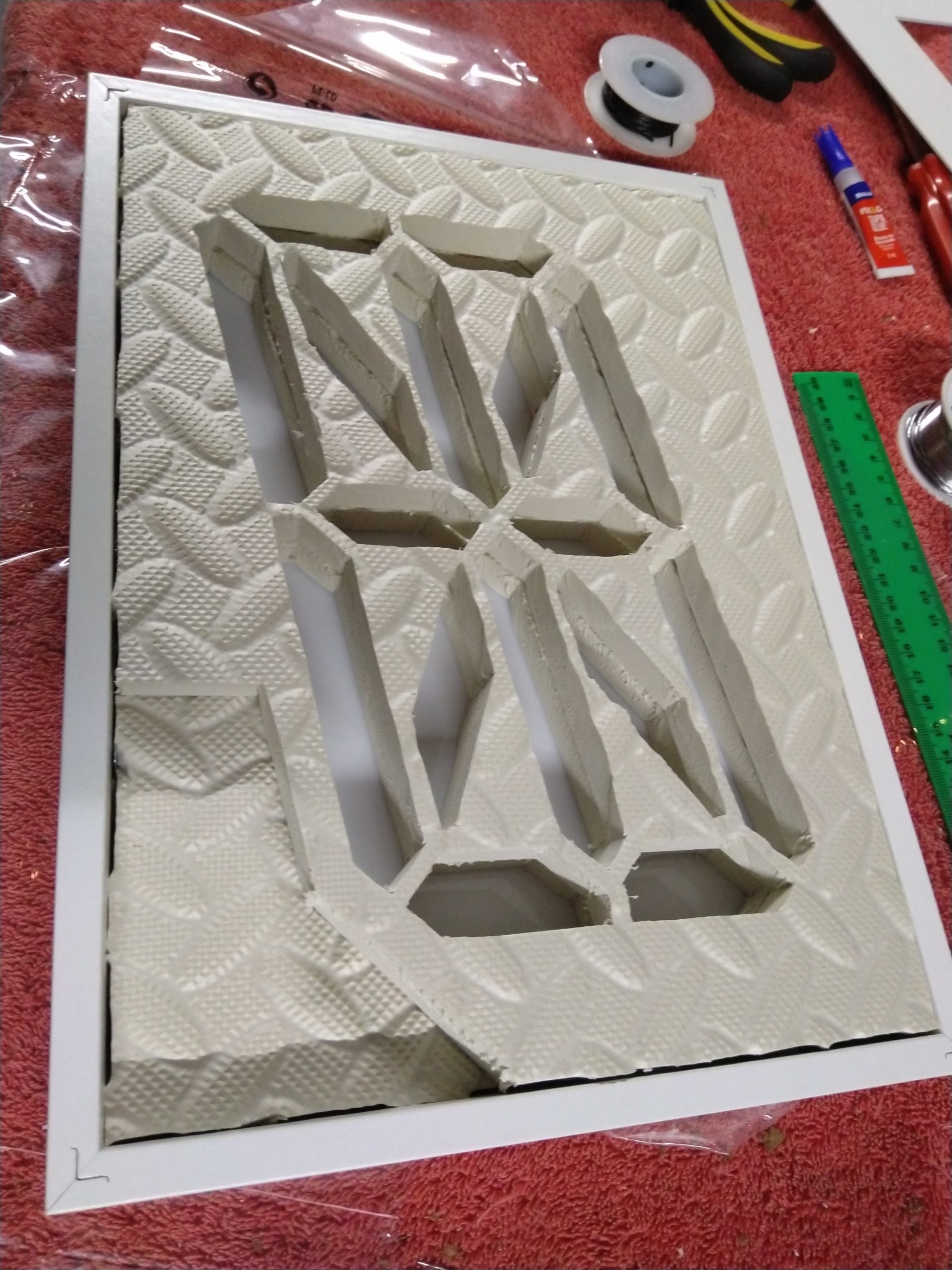
With enough foam pieces cut for a trial run it was time to see if the whole theory will work and how a finished digit might look as now’s the time I can still change things. A few cuts to make room for the double shift register board from earlier, and a trial run with the frame clamped together it looks good! So I assembled two complete digits as I couldn’t go any further without the veroboard.

Fixing the flickering
In this time I tried a whole lot of different methods to control the latch pin. I modified the reset pin to have a voltage divider which gave me 2.5 pins but no combination worked. In the end I had success with the Shift1 theory by Roman Black.
The general idea is with a resistor and a tiny capacitor, the shift register can be tricked in to believing it has received a 0 or a 1 just by making the clock pulse different lengths.
The timings had to be modified due to the Arduino slowness with the digitalWrite function, but with a bit of calculating and trial and error it seemed good! This allowed me to use just two pins out of the ATTiny85, one for clock/data using this method, the other for latch. This will drive 96+ individual outputs without the flicker. Thanks Roman!

Mass Production
All the materials have arrived (for now), it’s back to the production line to make the remaining digits. First was the control boards that house the shift registers. I had come up with a simple pin plug method (using headers and pins as shown) so that these digits could be sealed and self contained, and just joined by a simple 5 pin cable. I have also moved the diode to the Vin of these boards to further strengthen the standalone conept of it.


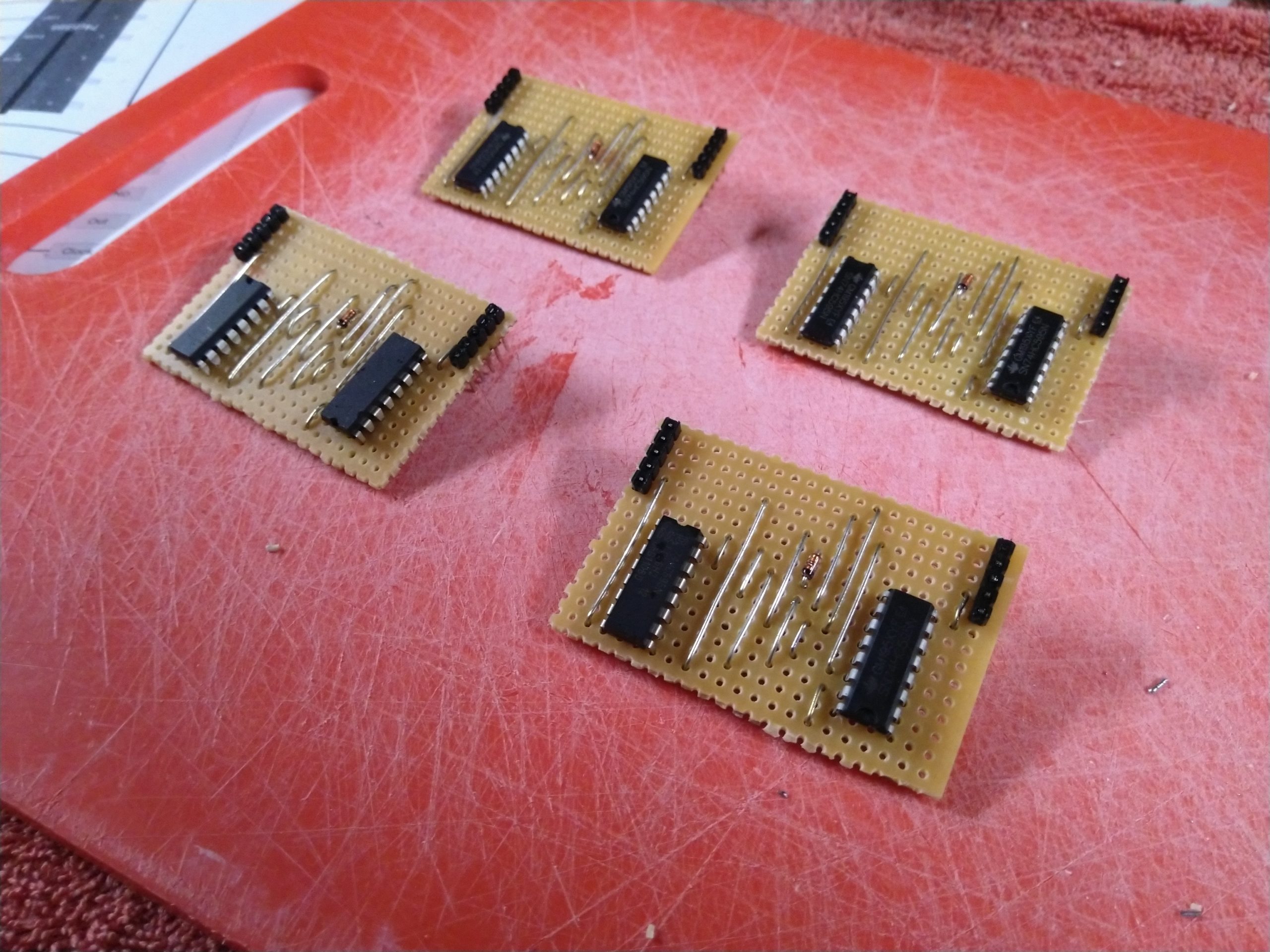

Once again, make sure to test the shift registers before soldering! I had to swap out one of these, another I soldered one track over from where it should be, and there is another slightly faulty one in here that I have yet to change. So out of 12 shift registers I had 2 faulty units.
With the boards all done it’s back to foam. I had 10 more to go meaning 10+ hours of cutting.

Enough foam done for now. I had discovered the second faulty shift register here and my new order hadn’t arrived so I knew I was two digits down. May as well get to the wiring for two of them. I t was a chance to try and make the process a little more efficient so I swapped from stranded core to solid core ethernet, and adjusted where each pair soldered to and which side it went to. Each board got a little nicer. If I had to do about 8 or 10 digits I think I would have worked out the nicest layout.
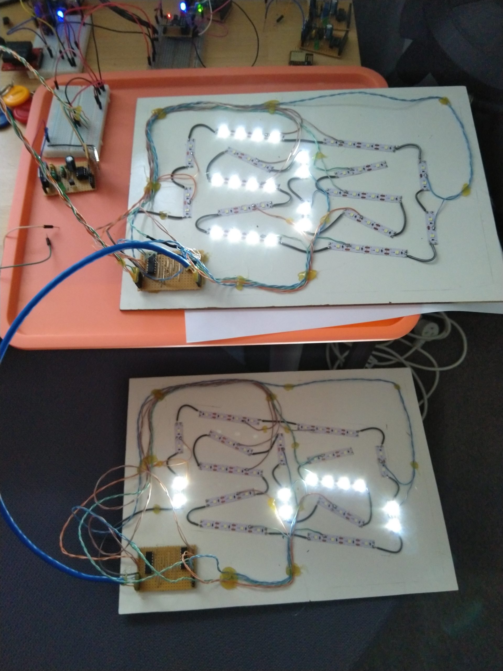
With 4 digits now complete, it was worth testing them. I made a few simple join cables out of solid core ethernet and headers, and assembled it all wherever I had room.

This gave me a chance to further diagnose if any shift registers and boards were giving grief. This is where you can see the faulty/end digit sitting on the stool unused. All the others seemed ok to be in any order.

Last hurdle

All parts had arrived including more sockets as I had run out. All attempts to retrieve some from old boards failed. I made another join cable, fixed the remaining lone digit with the new shift register, and made the controlling board a little more solid rather than using a breadboard. It was time to test five digits.
Final resting place
Another weekend and I had time to sort out the remaining issues enough to try all 6 digits.
A few things were done to allow this. I added brownout detection to the controlling ATTiny85 which prevented the settings from corrupting on power loss. This meant I could configure a chip on the bench, then plug it in to the display board while everything stayed a-ok, almost like a cartridge.
Then I found a few code optimisations to allow some extra characters to fit in the 8k of memory. This bumped the buffer up to 120 and allowed for symbols. I can now show a properly formatted JSON!
Stop the bleeding
The light bleed between digit segments is significant especially at night where the letters aren’t as clear. This is enough to consider fixing it. The best way I have thought of so far is to use white silicon between the layers and the board in order to remove the gaps. I know it won’t be perfect but it should do.
While trying some new cables it pulled a pin out of the end digit which has always acted a little off, so this will be my guinea pig.


With all my silicone used up I got 3 digits done. Time to see if it made a difference.


If you guessed the siliconed ones were on the right, you were correct! It does make a decent enough difference. Not 100% but good enough. It will be interesting to see how it appears at night.
Where to now?
The shift1 timings have been changed but some odd corruption still occurs when certain sequences of characters are pushed through. Unsure how to solve this unless maybe putting a longer delay between clock cycles.
I have removed the “——” pattern each time it updates, so that it will just sit on the last shown message instead which will be less jarring.
Then it’s over to finding a nice way to dim the display at night, and sticking all the controlling bits in a box. The dimming might be able to be done by way of a diode, but given the shifting at 3.3v and the shift registers are at 5v it gets a little tricky. Stay tuned!
Take a look at my MOSFET board project to shift brighter lights!
8 Months on…
I have been developing the main board that powers this and it’s finally in a good state, so it was time to swap the giant display over to the new resourciboard based implementation.
Why bother changing what works? So here’s what the new board gives it:
- Now has dual ATTiny85’s, one of them being the BIOS. This frees up a few kilobytes of code space in the main APP chip so I can do more effects
- Thanks to the BIOS controlling the MOSFET, I now have 3 pins free! This means no more shift1 trickery – the shift registers are controlled with 3 wires instead of two. This might make the characters more stable.
- It will actually fit in the enclosure. I don’t have a nice way to bring the wires out yet but there is enough room.
- The new firmware is far more reliable in fetching the web content. The previous code would often fetch the headers, maybe 25 – 50% of the time.
- The code now has its own pseudo RTC so it no-longer needs to fetch the day, date, etc. as the text to display. It can calculate all of these on the fly.
The only downside is that I mistakenly destroyed one of the digits with too much voltage. Unsure if the entire thing is fried or just the shift registers, but I need to take all the digits apart to add bypass capacitors and fix some specific segments that have failed anyway so it can be repaired at the same time.
Lets see if this board works for 8 more months.