Since the Rally Car project I have been digging around other old (or “vintage”) lego sets and I decided to clean and rebuild them all. But I have a new victim for my newfangled electronics knowledge…
The original Lego Technic Control Centre
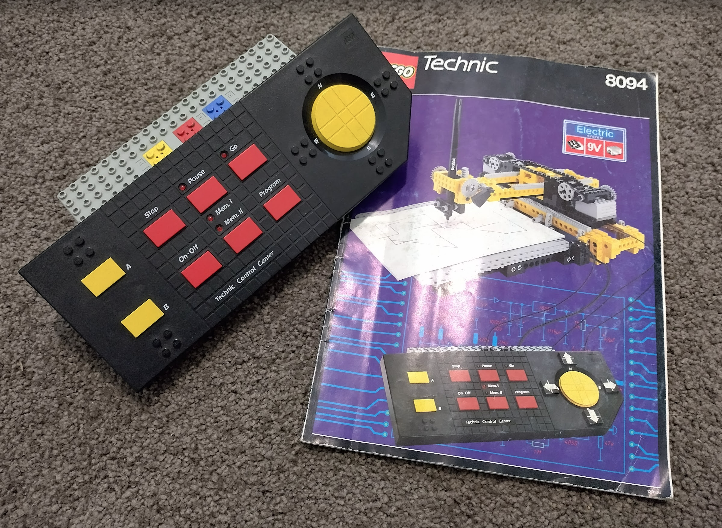
This set arrived in the 90’s and allowed for the programming of the motors to a pattern that can be repeated over and over. I won’t be using the actual control centre for this, but rather duplicating that setup via the same ResourciBoard as the rally car project, but it will need the shift register addition, which will also require the old shift1 trick from a year ago as I’ll only have two pins.
This could easily be achieved with a standard arduino uno but where’s the fun in that?
Assembling the model
I decided the plotter which was the primary model in the set wasn’t suitable as you can only draw once, and I don’t want to stray from the original kit much by adding more motors, changing things, etc. So the most interesting and impressive model is the crane, as it allows for 3 functions using just two motors.
First step was to collect all the parts to make sure I still had them, and then give them all a good wash of 30 years of dust.
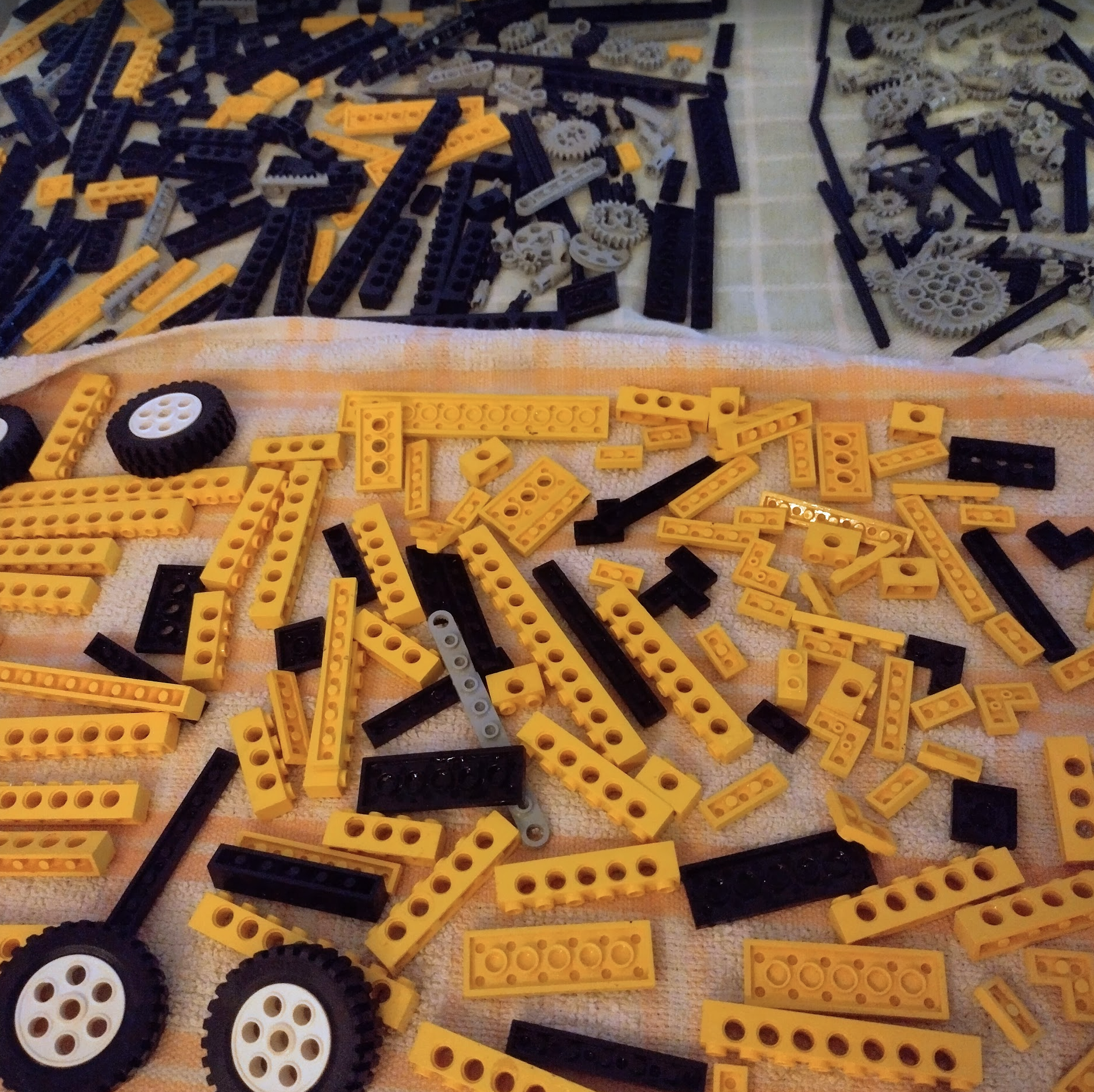
This model is split in to two parts. The primarily black parts are for the lower half of the crane, the yellow for the top half. So I could build it in two goes.

As pulleys don’t last 30 years, I had to swap out the pulley part of this with a small and medium sized gear to do the same job.
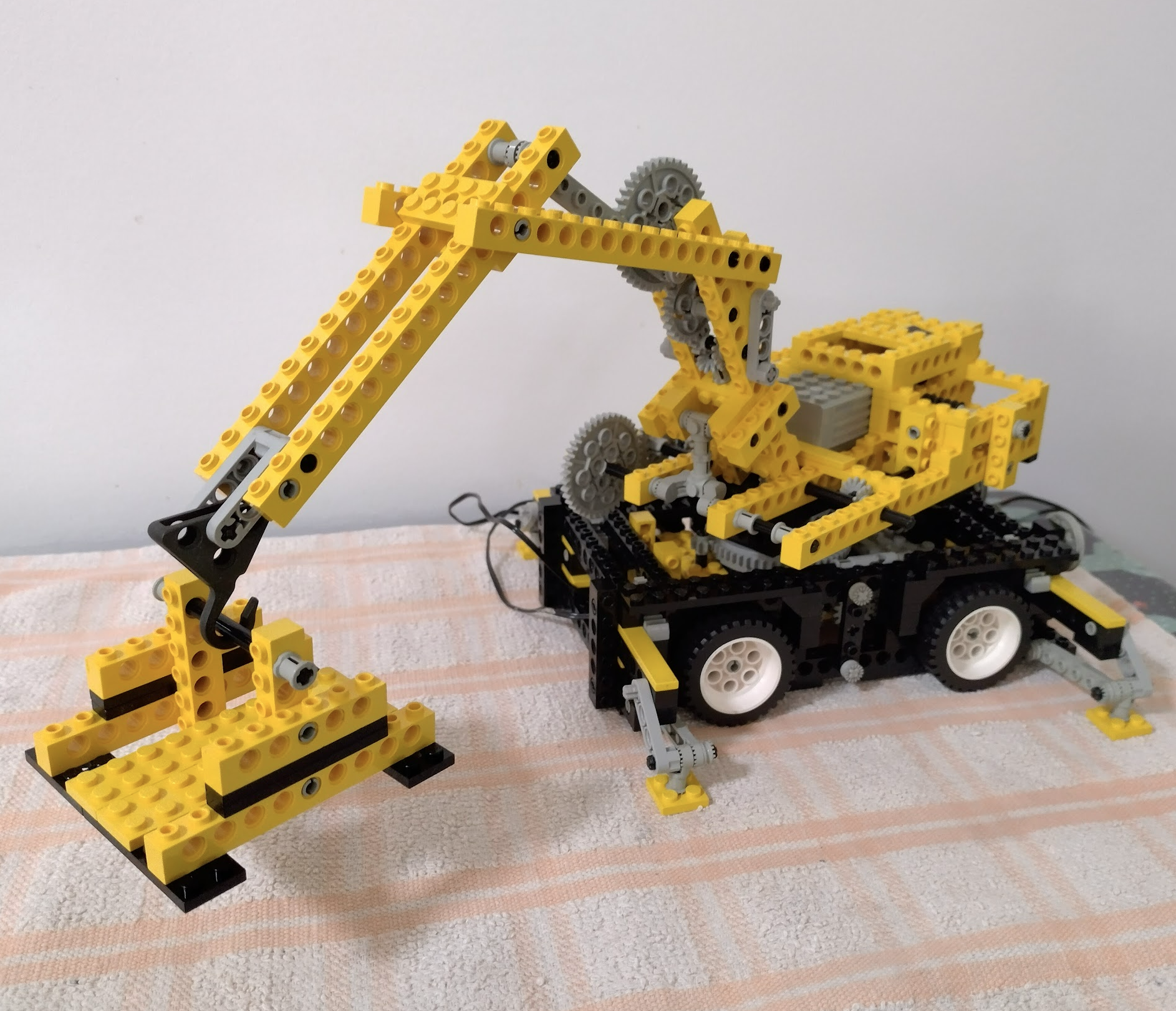
Just like the lower half, the top half contained a pulley to drive the little back and forth gear switch. This was swapped out with a small and medium gear just like the lower half however it then caused issues with the side gears of the switch mechanism interfering with the motor. I had to remove the spacers from those side gears, and also swap out the two flat gears on the switch itself with a slightly larger gear, and remove one layer of the yellow 2x blocks on the switch “handle” so the gear would reach. This was then tested and all worked perfectly if not a little noisy. Who needs pulleys!
Hooking it up
This model is a test case for getting more robotics features to the ResourciBoard – the issue being I only have 3 pins to play with. I would ideally like inputs alongside outputs but I haven’t worked out a way to achieve that. However I think I have worked out how to get a couple of motors along with multiple servos.
The rallycar project used one motor (in forward and reverse) with one servo. The servo only required one “analogue” pin for the pulse, and the motor required two digitals to tell it whether to go forwards and backwards. I worked out early on that if I add a shift register in along with the Shift1 trick, I can control as many motors as I like. But I could only do one servo as it requires the analogue signal.
I finally figured out it may be possible to send the analogue signal to multiple servos, and just connect the ground to the one that needs to listen for it. That way only one servo can move at a time but I can have as many hooked up as I want alongside the regular forward/backwards motors.

With this combination I can make very complex robots with many motors, servos, and digital outputs. They just can’t think for themselves as there’s no inputs.
Off to writing the websocket code!
It’s Alive!
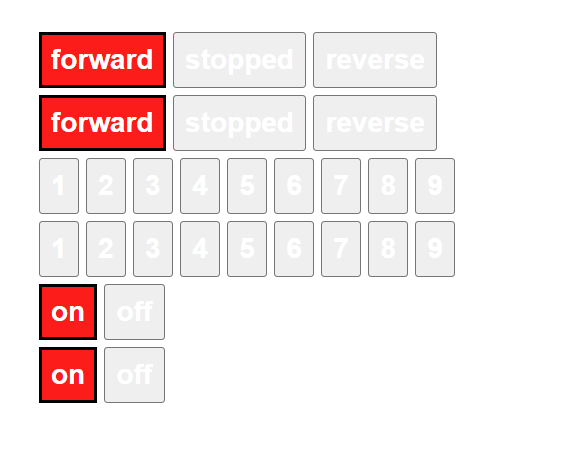
After a lot of debugging to track down a set of faulty wires, the circuit is now proven and controllable via websockets.

This has exposed an issue with the smaller servo which seems to contain no memory of the pulse signal. The MG90S moves to the correct point in one go, however the other servo moves a tiny amount each time. So a few more of the MG90S’s are now on their way.
The theory is this can be daisychained to control as many devices as possible with a few limitations – one servo at a time. With the other large limitation being there’s no inputs. The device can’t “think”, it can only do. Unfortunately I haven’t worked out a nifty way to hook up a 74HC195 to this and have it swap between inputs and outputs for those two pins on the ATTiny85.
So the next bit is to hook up the crane to this, along with a camera and see if it can all be controlled remotely from a phone.