This content is incomplete and may be inaccurate, feel free to look around & please check back later for updates.
I’ve been getting in to less-than-genuine lego-style sets lately which while they scratch that itch for much less cost, they do have some areas that require a little more effort. I’m documenting what I discover as I go here so that you can be aware.
Buy official sets.
If you want top quality, a pleasant and trouble-free building experience, branded/licensed items, and knowing that so much time has been put in to making sure everything works and runs, just buy the official set. Otherwise if you want suffering and sore thumbs but at a low cost, keep reading…
So why buy non-genuine sets?
Price is the main one. A normally $650 set can be found for around $50. Motorised sets reduce the gap a little. And if you’re in it for the construction and not necessarily 100% functionality, you still get the build experience, a nice model at the end, and hopefully it’ll all work good enough too!
Do your research though. If a set has sold 1000 of them, pretty good chance it’s fine. Pneumatics aren’t leak-proof so be aware of that with some sets. Licensed products are renamed or colours are changed just enough. What I find great is you can sometimes get long discontinued sets again if you missed out on it 10 years ago.

Everything is very slightly off
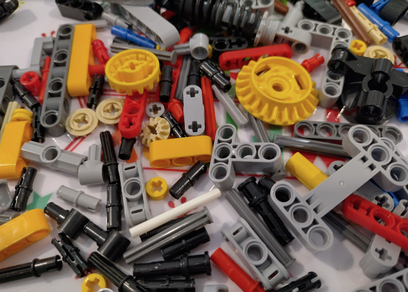
While the pieces all look fantastic just like the real thing, the tolerances are just not quite right. It’s impressive and for the beams and such it isn’t noticeable. But when you get to the axles, gears, and connectors it starts to show.


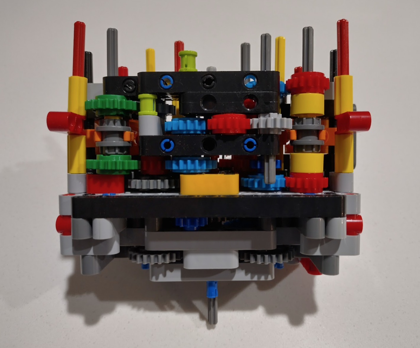
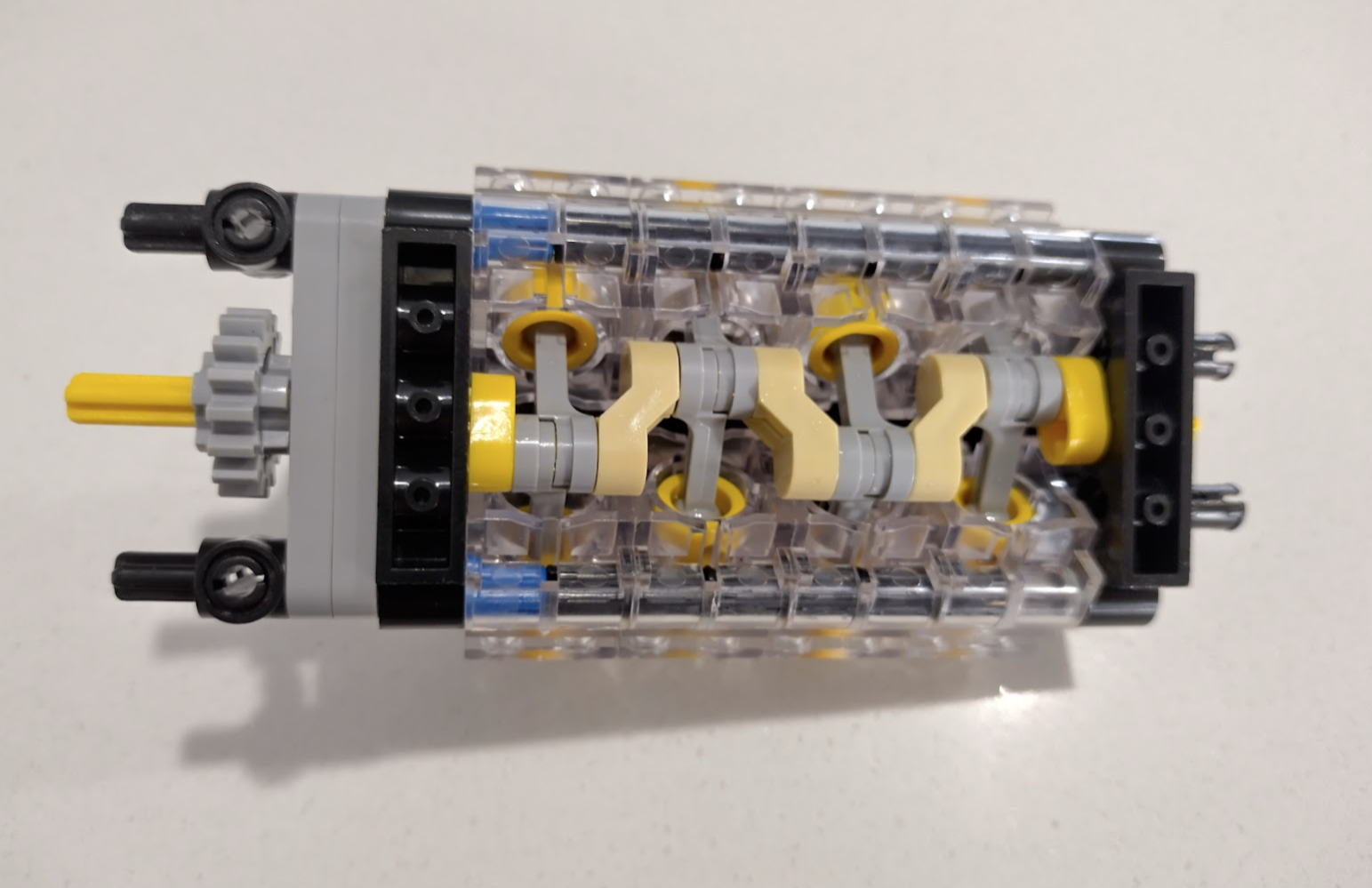
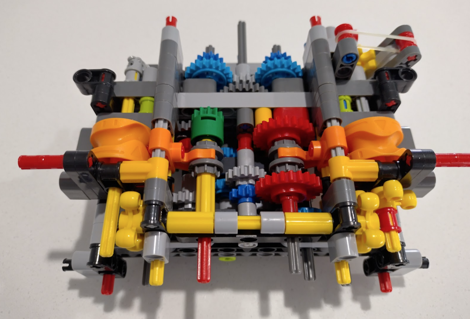
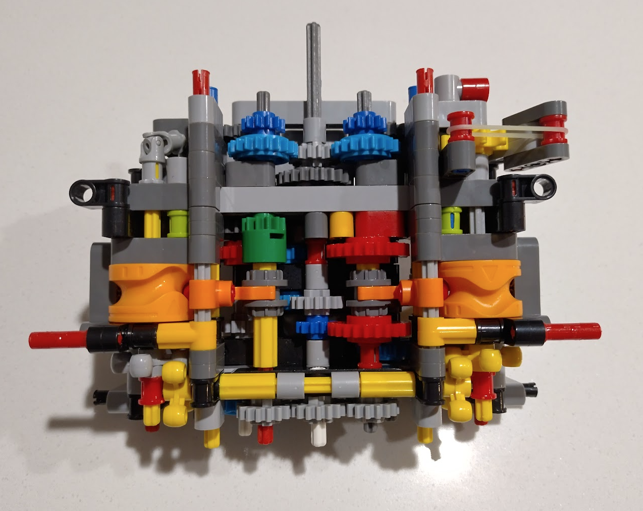
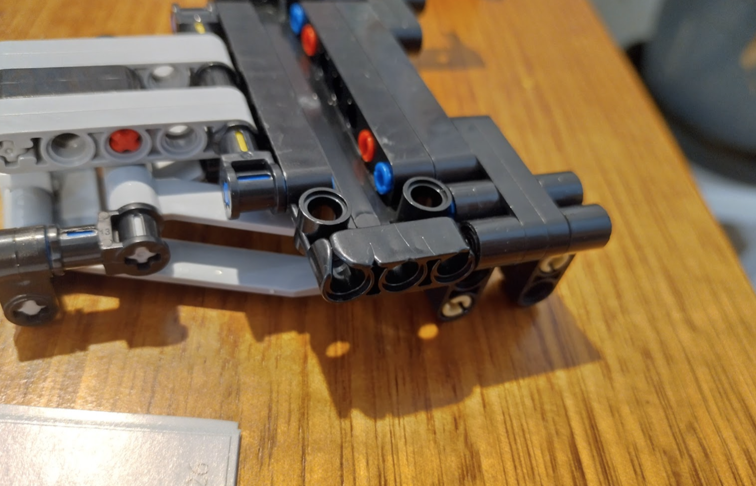
This is a good example of where the tolerances change it a little. Some of these gears are held in by the light coloured “snap-in” axel pieces. These don’t spin as easily as they probably should, which makes this whole area a little different to the official version.
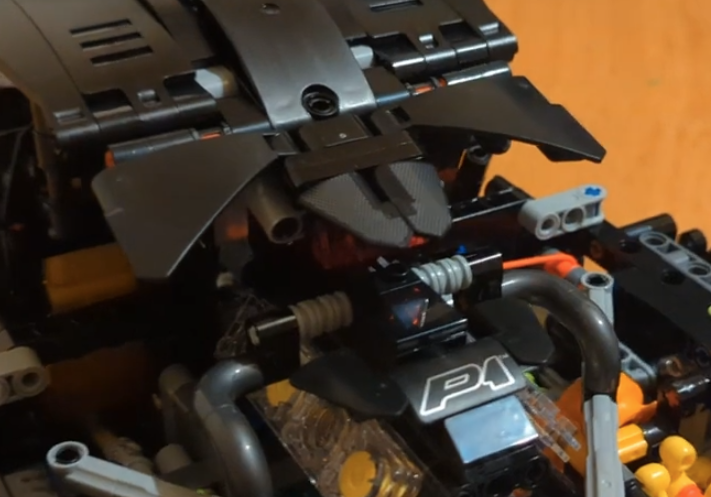
And while we’re here I spent a bit of time trying to work out what the two levers do – specifically the left one as it never seems to end up connecting to anything that I can see.
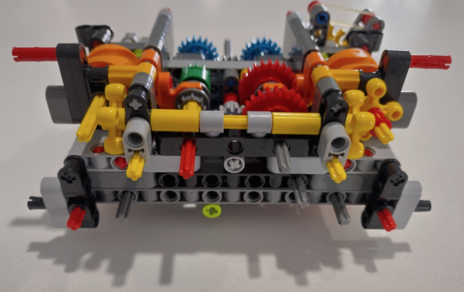
The right hand lever switches between v8 (left position/forwards), neutral (centre as shown), and electric (the motor represented by the big grey circles at the right hand side of the image).
The left hand lever (at the front of the car) when angled to the left (forwards), allows the electric motor to be engaged regardless of what the other lever is doing – but it’s meant to allow you to engage the electric at the same time as the v8 to represent a hybrid drivetrain.
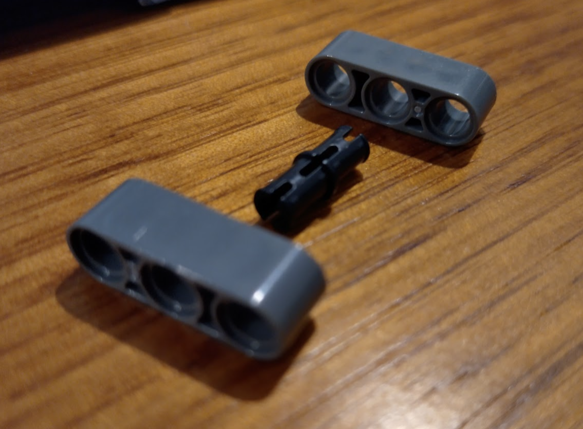
This makes assembly less “easy” and more of a problem solving exercise, with the unfortunate addition of sore thumbs.
Make sure you have these in your toolkit and you can solve most of the issues.
- Pliers
- A small flat screwdriver
- Stanley knife
- Silicon Grease/Oil
- Very fine (wet/dry) sandpaper
- Superglue
When things are very wrong
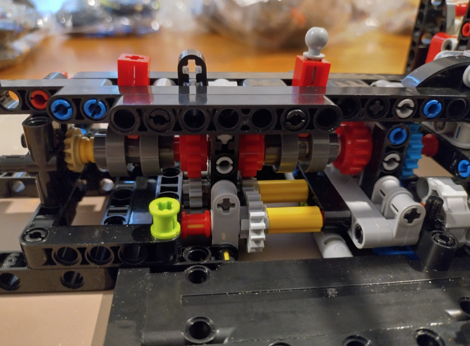
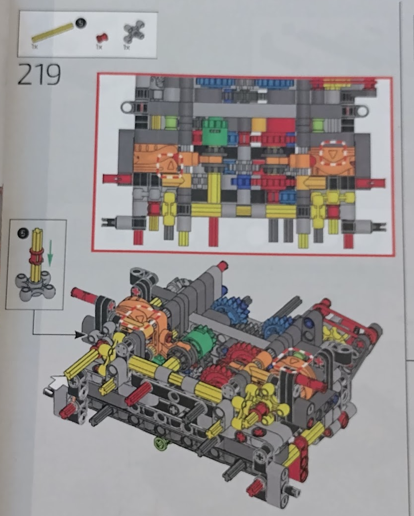
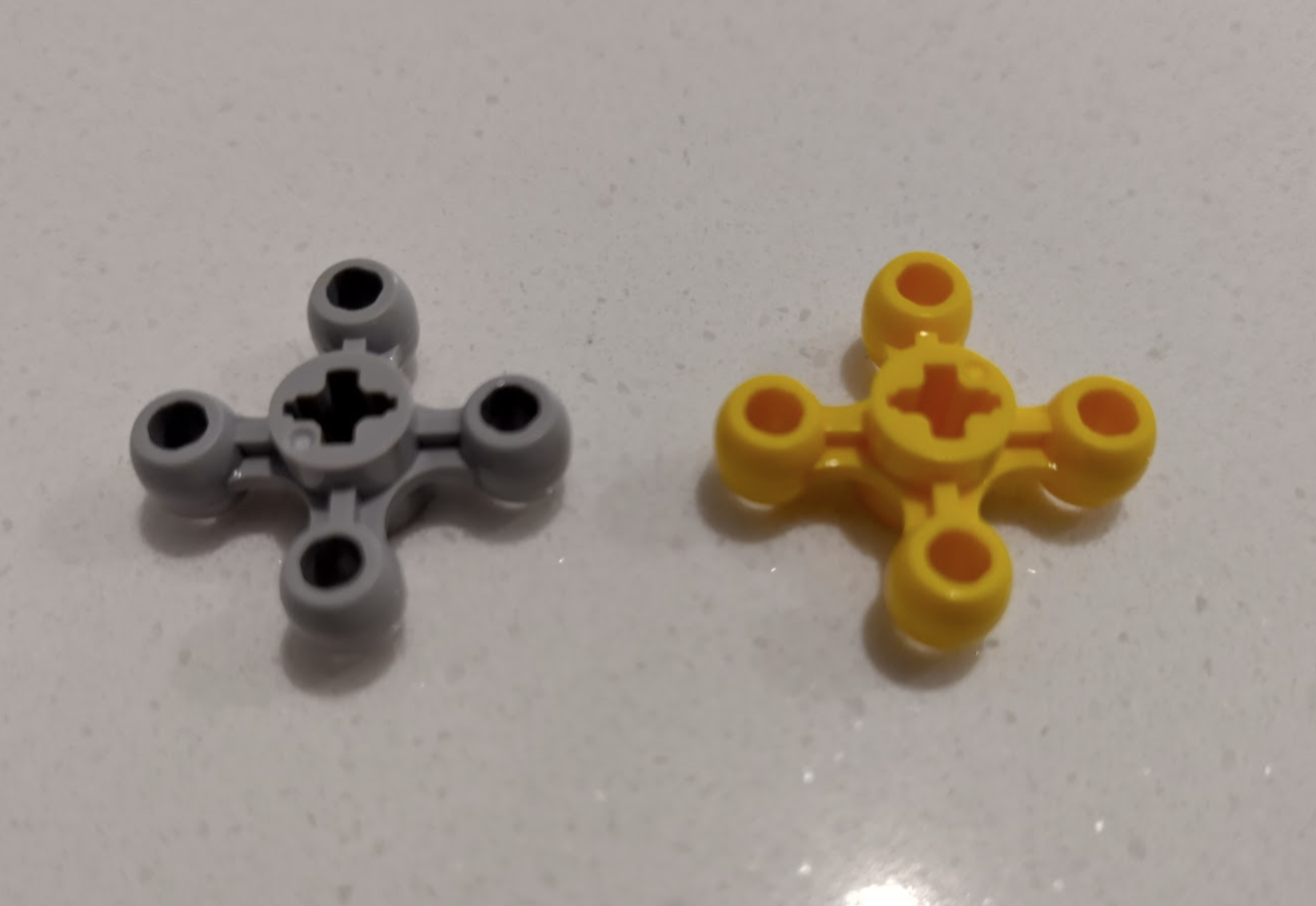
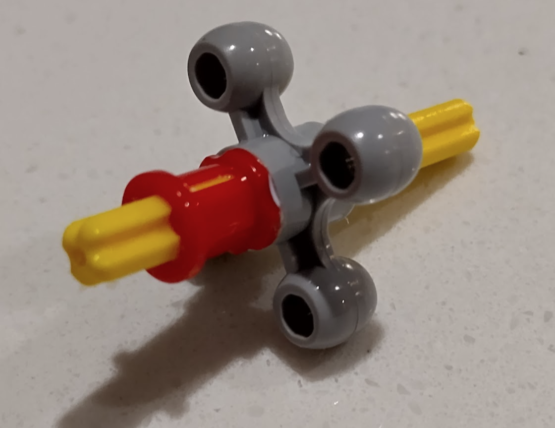
With this set I couldn’t get the orange arrows lined up 100% correctly but close, then wondered why they put a grey one in at all – why not just use 3 yellows. Then it clicked why I couldn’t get the large orange wheels to line up to where the instructions wanted them. Officially different colours are sometimes used to indicate slight changes. Some identical connectors are different colours to indicate whether they are looser or tighter. In this case the two knobby gear things are meant to have different axle orientations. The grey is meant to be 45 degrees different.
You can see I’m not the only one to discover this.
https://www.reddit.com/r/lepin/s/c9VFU6wWSL
My guess is that they used the same mould for both parts thinking it’s just a colour change.
This is the official part (5405) shows the correct axle placement, and can be swapped in.
https://www.brickowl.com/au/catalog/lego-gear-with-4-knobs-5405
My solution is to make this work by drilling out the middle and glue it assembled to the red stopper & axle.
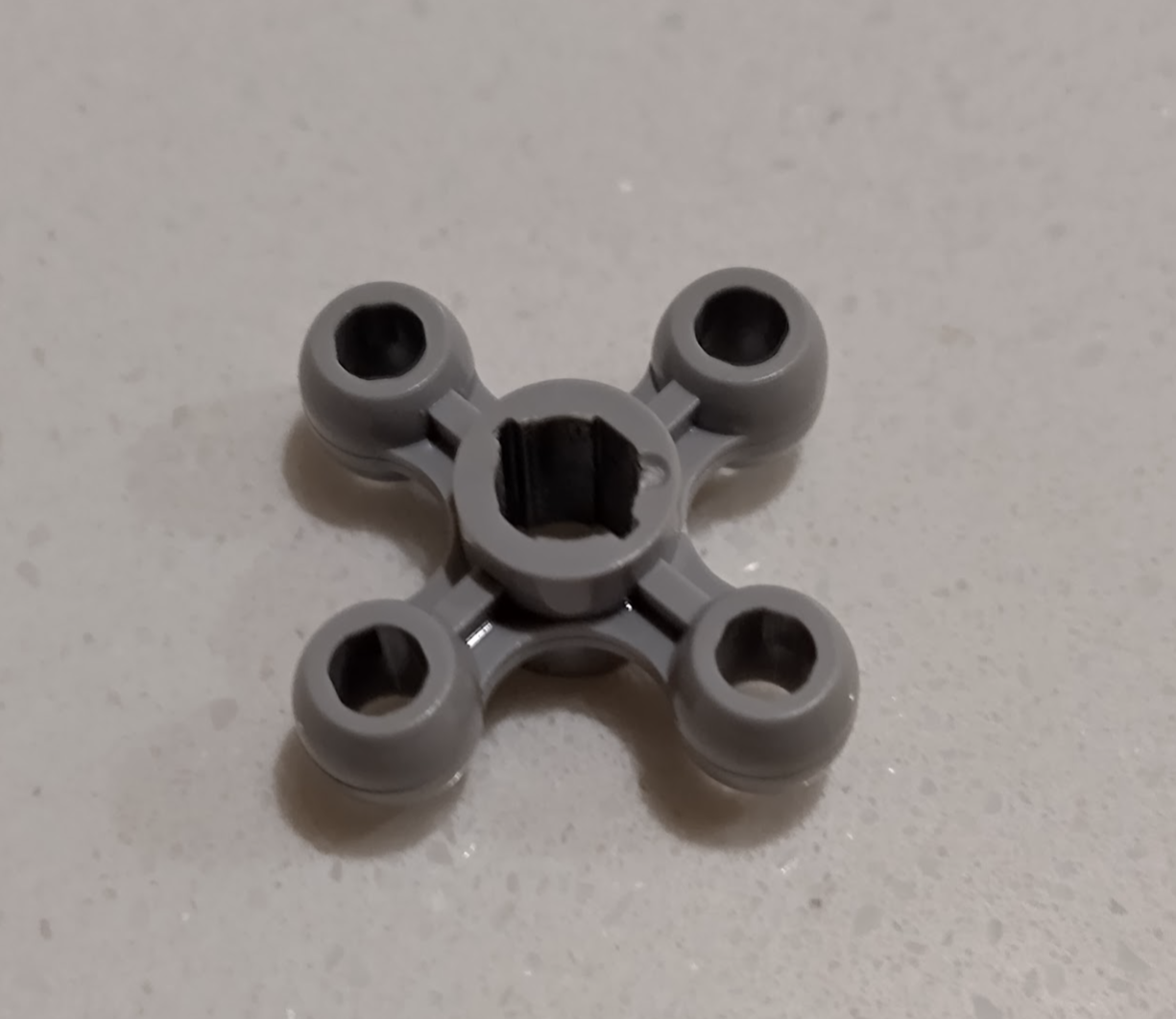
All works as intended, and not an issue as this isn’t planned to be taken apart again – although it still can just a slightly different way.
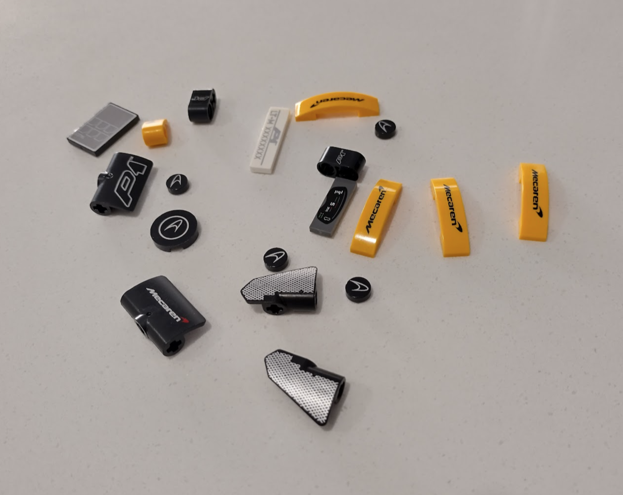
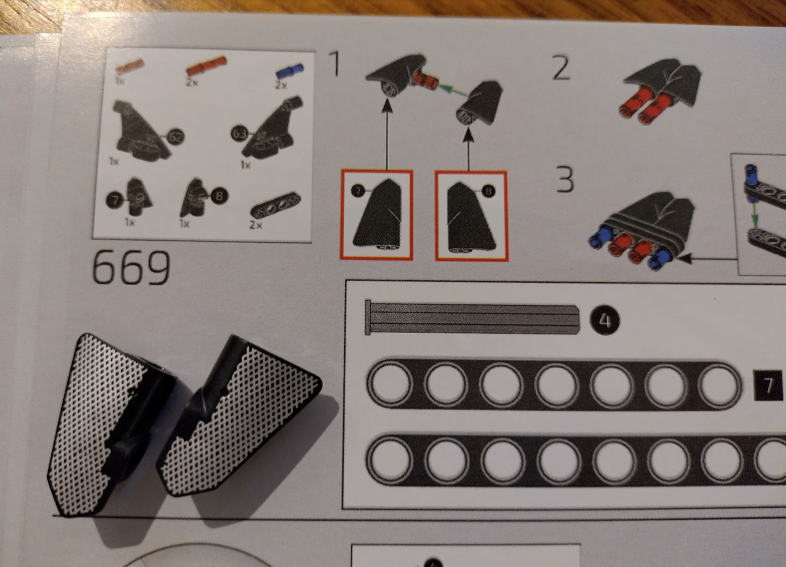
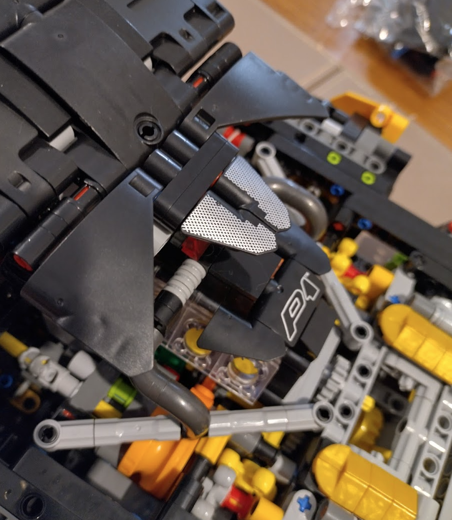
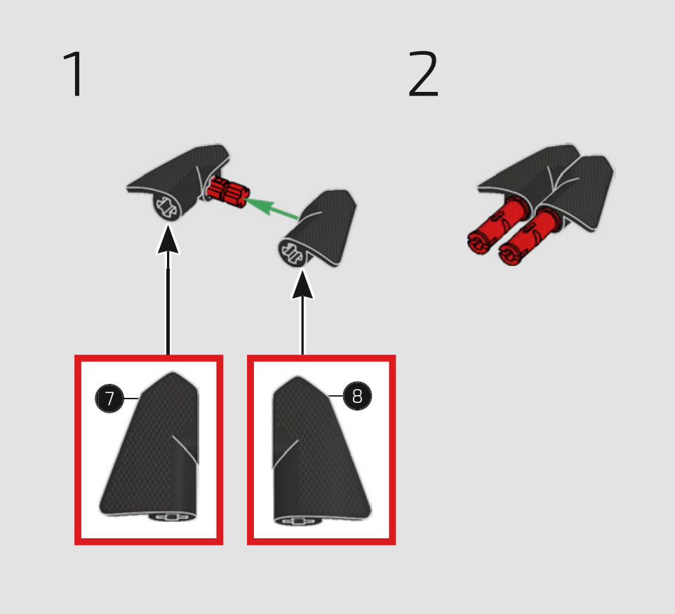
Step 669
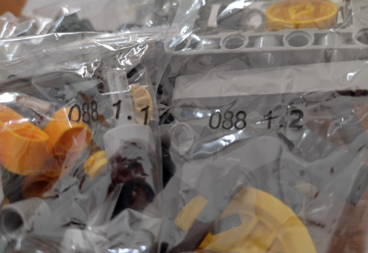
Here’s one that had me looking for pieces for a while. The two black “wing” looking pieces weren’t in the packets for this step, but I did have two mesh printed ones in the special parts. This isn’t clear in the manual, and the official manual (and photos of the set) aren’t obvious either as it’s very faint whereas mine are brightly printed. Hope this helps someone!
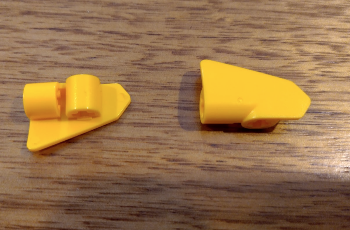
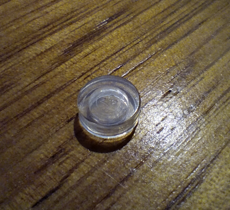
Missing/deformed pieces.
Near the final steps of this particular build I discovered two missing pieces – there was an orange/yellow odd plastic bit in the bag which I think must have been counted as one of the pieces, the other was a clear headlight lense where I can understand if it was overlooked. And one had a slight moulding issue but it has no problem working, and isn’t visible.
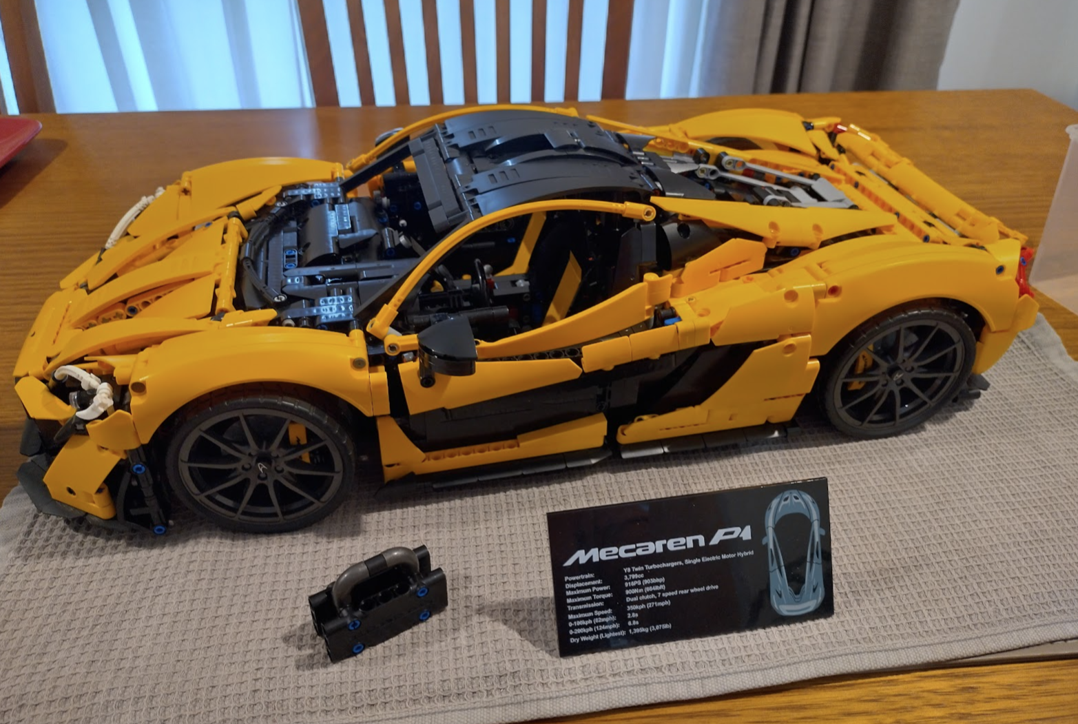
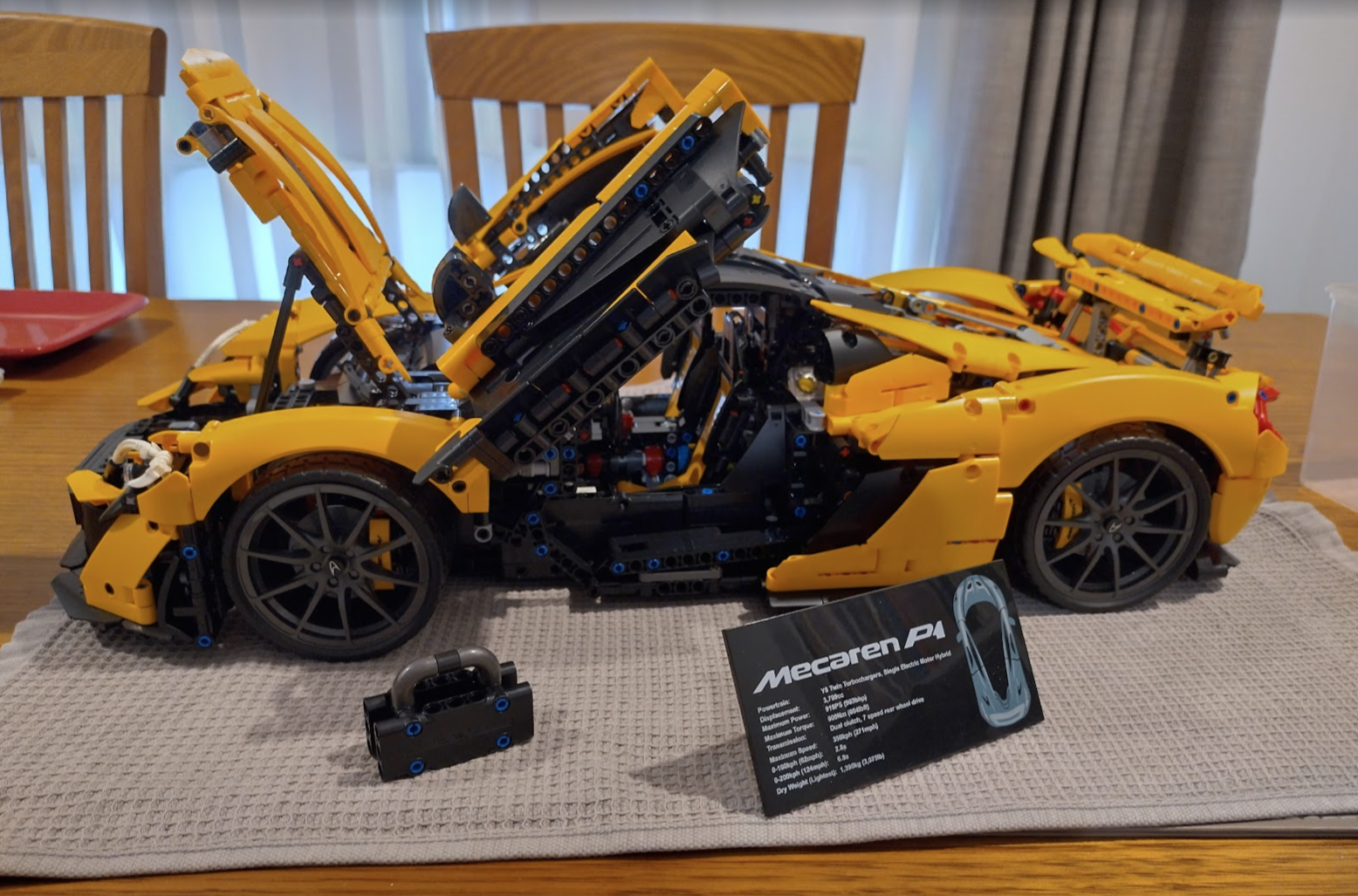
Does it work?
The completed set works as I would expect it to. Everything moves, the engine works smoothly in low revving gears, clicky in higher gears. But I’ve had the exact same issues or even worse in the official Landrover Defender set. So I’d say it’s a success – just be ready to use tools, attack some pieces with sandpaper, and use a lot of silicone grease.
What about other sets?
I have since purchased a few more. The Arocs set comes in at a little over double the cost of the Mecaren, but the quality of the connectors and gears is better. Less adjusting and the fingers don’t hurt. But there is still sanding required to get some areas to work smoothly – mainly the gears as the sides contain little injection bumps, and the gear’s teeth are slightly bigger so sometimes they grind where they shouldn’t, or they are a bit tight so you’ll need to sand some down occasionally.