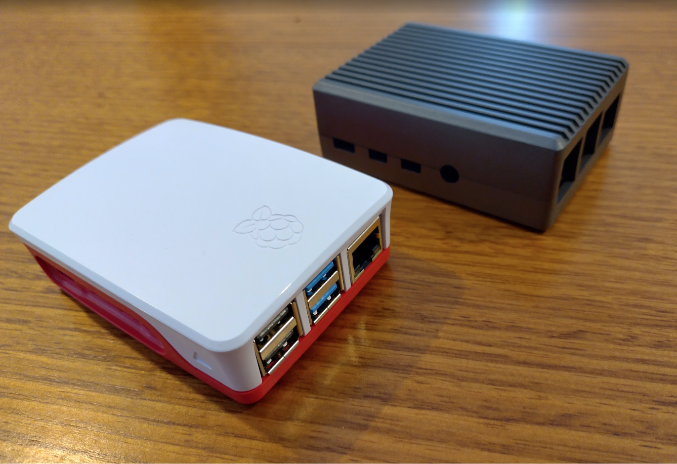
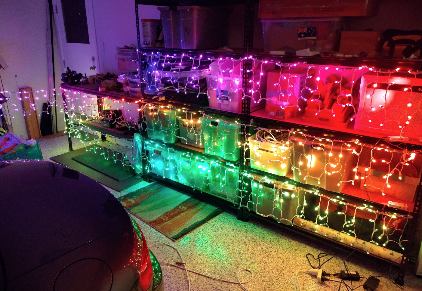
After initially going through the electronics way of attempting christmas lights, I have decided to do it the easier way as there’s enough to go wrong as it is. My goal is to have 4 separate icicle-style areas of lights powered by 3 ESP32 WLED controllers, all linked together via a remote Raspberry Pi FPP sequencer so that they create a large canvas of sorts eg. a circle could expand from the centre of the house all the way to the outside edges. This will all be scheduled/designed using xlights like the original article. Lezduit!
Led Controllers
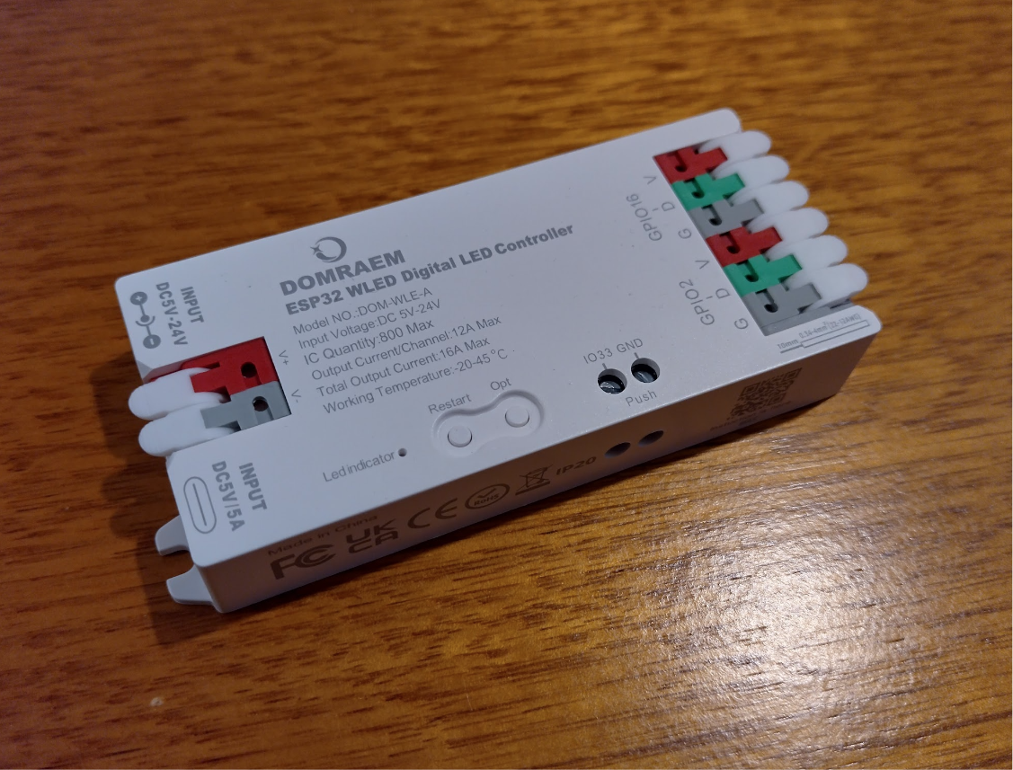
Initially I have purchased a few ESP32 based modules. These are basically the same as what I was building manually just it’s all neatly tucked in a fused box that I don’t have to worry about. For about $20 each it’s worth it, and they can drive two strings/channels of lights each at 12v.
These can work standalone if you would like a simple unsynchronised display eg. twinkling or sparkles or such, because you can use the build in numerous wled patterns. But I think I can go a little better…
Update: It is possible to sync multiple wled boxes together, I’m not sure how much they sync – my goal is to run all the leds as one giant canvas. So if you’re just wanting a synced light display with the fantastic wled effects then you can skip the Raspberry Pi & xlights portion of this.
Notes
- Get the proper ESP32 versions as ESP8266 is losing support in wled.
- These are very easy to update to the latest wled (16 currently)
- Make sure when you reset it all, to remove the relay setting, and set the push button to 33.
- Two of mine decided to stop pushing voltage through to the output side. I couldn’t find anything obvious inside it – there might be some sort of solid state fuse thing. I’m using 12v everywhere anyway so I’m just tapping into the input terminals.
Leds
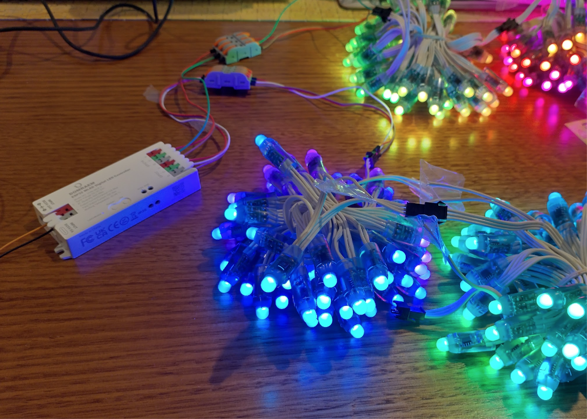
For leds I’m going with the old WS2811 based 12v pixels, with white wiring to look like snow a bit, and long enough to create pretend icicles of 5 leds long. Theres a technique to this which I’ll detail below.
I’ll need about $200 of led strings to achieve all the areas.
Synchronising
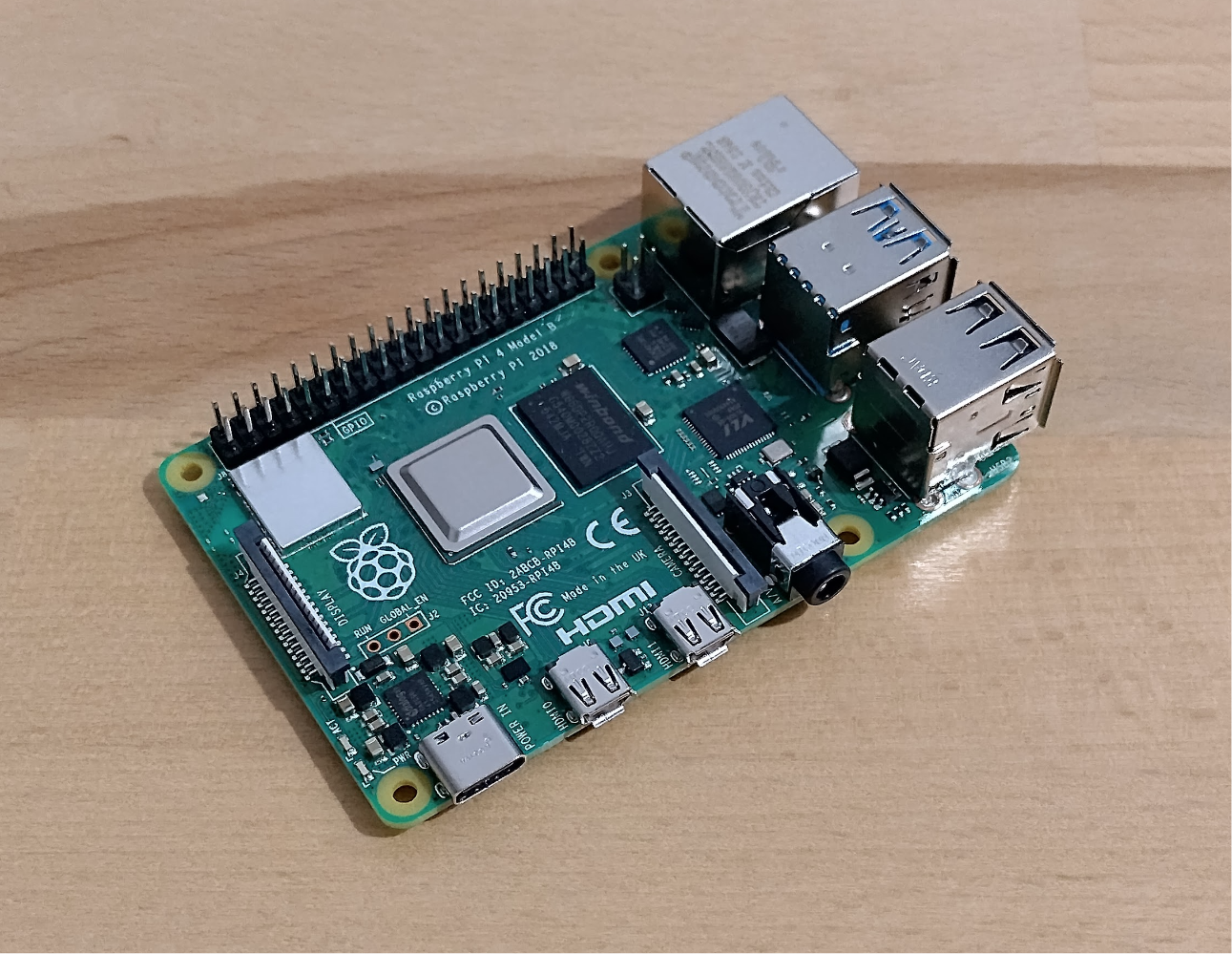
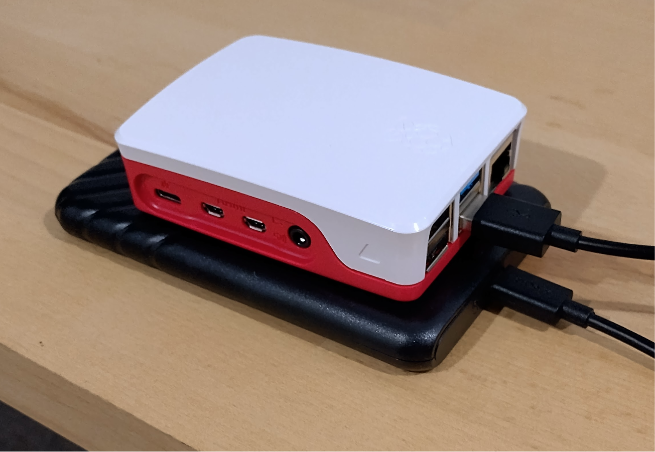
To drive a synchronised signal to those you generally need a dedicated single board device. The device requires WiFi at least, but I’m looking to have my board send the signals to a dedicated WiFi router over ethernet & hopefully broadcast the data (DDP Unicast) to reduce as much lag as possible. The easiest option is Raspberry Pi which are costly now due to the ram shortage, however I managed to pick up a Raspberry Pi 4 for $60 + a case. This will connect to my local WiFi for updates, and to the dedicated router over ethernet.
The thing with Raspberry Pi’s is they don’t come with storage. So the default option is to generally get a quality SD card which costs $50 or so and could fail. However I discovered these boards can boot a USB drive and I have a few old SSD’s around. A cheap $11 caddy later and I now hopefully have a reliable FPP device, that’s more money to spend on Leds and wiring!
Update: I’m having a lot of trouble with booting the Raspberry Pi 4 in general. I have attempted different images, different drives, different usb cords, usb keys, updating the eeprom on the raspberry pi 4. I’m just getting a solid green or a double-blinking green each second. Waiting on a micro hdmi to arrive so I can hopefully find out a bit more about what’s going on.
Update: Success! All hardware was perfect, I just needed to edit cmdline.txt on the drive after imaging, and change it from root=/dev/mmcblk0p2 to root=/dev/sda2 and everything started up perfectly within seconds.
Protip: If you’re wanting to connect fpp to your wifi, disable tethering and set your wifi ssid and such manually, then reset it.
WiFi
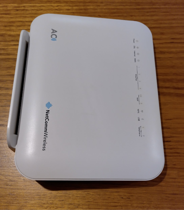
Running the display over wifi is generally frowned upon however it’s a cheap way to get started and hopefully good enough to do a very low intensity display. So the way to make it as solid and responsive as possible is to have the WLED devices on their own dedicated WiFi access point, and have the controller send the signals to the access point via ethernet. I happen to have an ex-modem router with wifi & ethernet ports, so that will be the backbone of this display.
Due to the wled devices being esp32’s, and to reduce interference, I’ll be disabling the 5g & running it all at 2.4ghz.
xLights
This will be a similar configuration to what was worked out in the previous article, however with DDP apparently universes aren’t required anymore so this will focus more on that side of things.
Turning a LED string into icicles
There’s a technique to this which took me a while to find out attributed to a petulka77 on doityourselfchristmas.com. The trick is to use a regular Pixels string, but place a small PVC clear pipe after every 5 (or however long you want your verticals to be) lights. That forces the string to be relatively straight and allows for somewhat good separation. Then this back and forth pattern (called serpentine) can be set in xLights (and wled 2d matrix if you’re not using xlights or fpp) making them work as icicles or even a rough matrix. Much cheaper than dedicated icicles, with a little better coverage given the randomness.
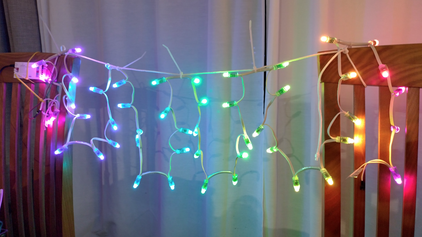
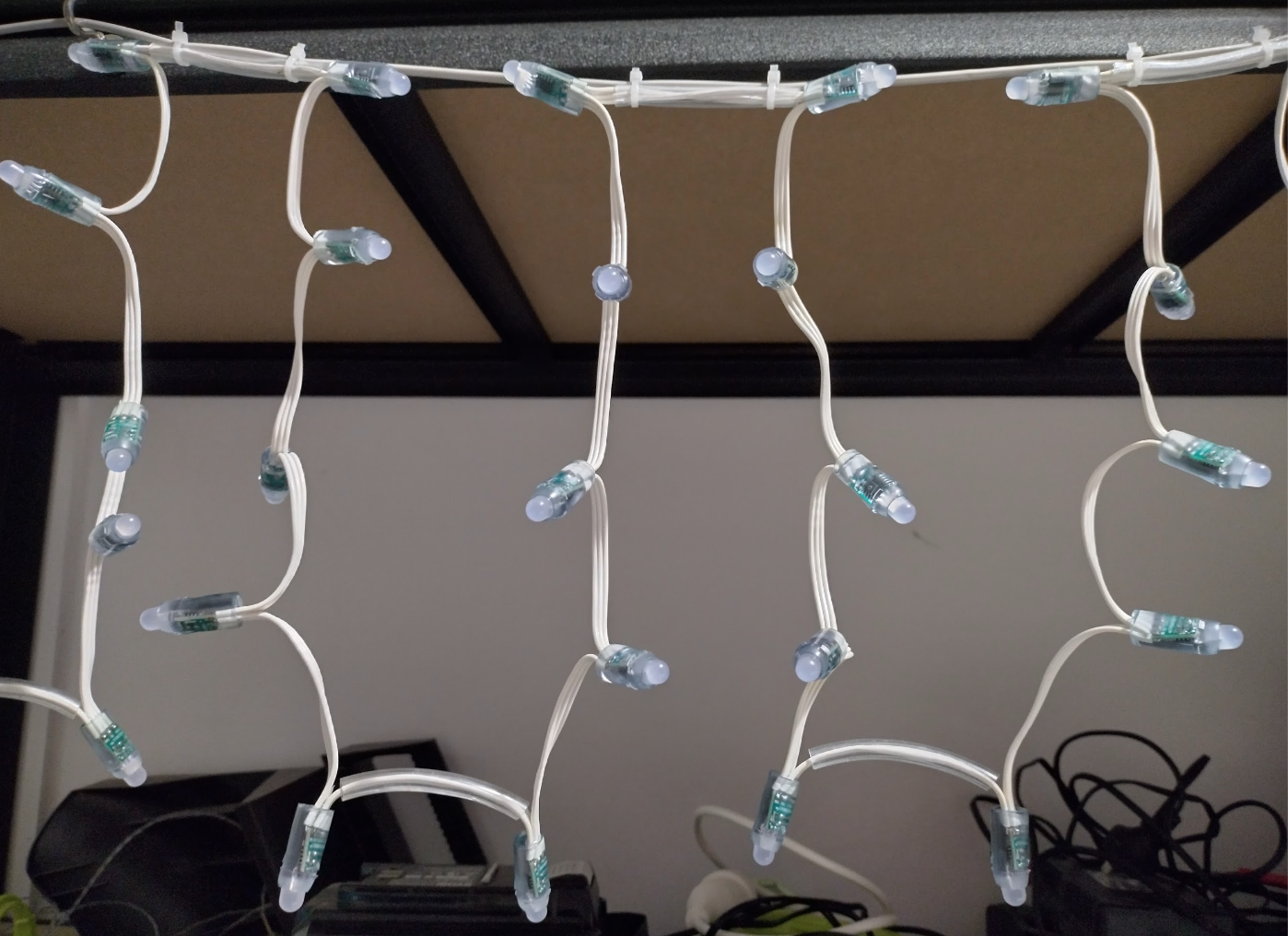
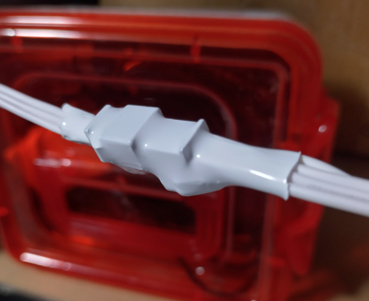
The test setup
xlights (wifi) -> (wifi) Raspberry pi (eth) -> (eth) router (wifi) -> (wifi) wleds (gpio16) -> pixels (arranged as icicles (polyline), alternating node drop)
All devices connecting to the router (ethernet & wifi) will have mac address assigned static ip’s – so they need to be delayed in switching on so the router can do its thing.