This is an ongoing project. Click here to read about Part 1, the initial concept. And click here to read about Part 2, the arranging and testing phase.

View a real-time 3d model here!
Now that the board has been designed and engineered, it’s over to sourcing all the components to make a few of these and streamline the assembly process.
The daughterboard or sub board
This whole board has been designed to hold a sub board above it to expand what it can do. This all fits within the enclosure still. I have been thinking about this during this process and I want a number of dedicated sub boards for things like GPS, OLED screens, pagers, dice kits, etc. But I also want a generic veroboard style so that custom circuits can be placed on top of this.
Initially the board had a giant cutout for the battery, but then the resourciboard has the option to run without a battery which is a lot of wasted space. This got me thinking – why not make it like the plastic model kits where a piece can be snapped out if needed.
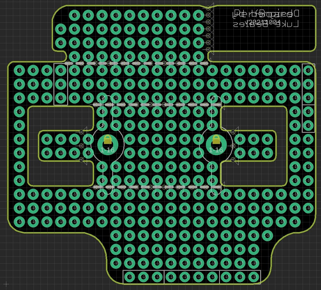
So that solves the middle battery part but there’s another way I can expand this. What if someone just wants the enclosure and a nicely fitting veroboard for a custom circuit within. This means I can make a second snappable part where the super capacitor and regulator/mosfet is. This has resulted in the following initial layout.

This has 3 purposes:
- A full veroboard to be used on its own or even stacked two on top of eachother within the enclosure
- Snap the top area off, and it will now fit snugly on top of the resourciboard when a battery isn’t required
- Snap the middle out and it can fit on top of a battery powered resourciboard.
Of course without the enclosure, it can be stacked as high as required. An arrangement such as the following is even possible.
- Full veroboard with no snaps removed
- Veroboard with all snaps removed
- Resourciboard

This lends itself to the flexible and multi-use nature of the ResourciBoard. I will have to refrain from sending this off to be printed until the original boards arrive however to make sure the spacing is all correct.
Snappable board adjustments
I tried a test fit with printouts and veroboard and everything fits ok so far, just the battery clips were taking up more room than I thought.
As a result I have moved a few things around and added a few holes to make the snaps a little cleaner, and added a fun info tag so that the manufacturer can put a serial number.


This arrangement supports the most amount of possibilities, and supports a tiny OLED, esp32cam, and GPS module for prototyping.
I’m not sure the board manufacturers will be too happy with this but let’s see, it’s been ordered!
They weren’t happy
An email came back asking me to check the tolerances and they were right, the soldermask was too close. So I have adjusted the pads and gaps and it now all looks good. Also made them all round to be more aesthetically pleasing.
This one should pass. Fingered crossed. For now here’s a few renders of how the whole ensemble could appear.


Of course with no areas removed, it will fit within the enclosure and can be a fully custom board, or it can sit above to create a 3 layer arrangement.
Now we wait.
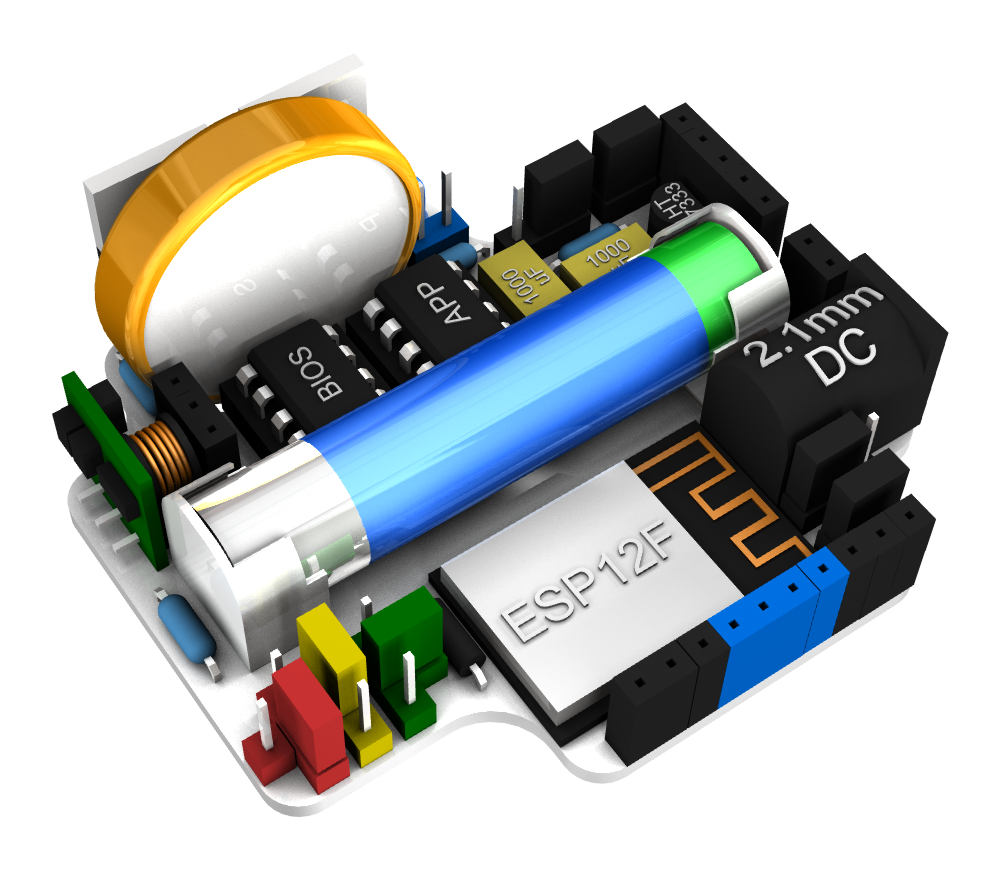
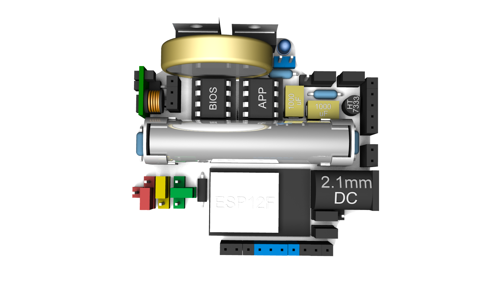
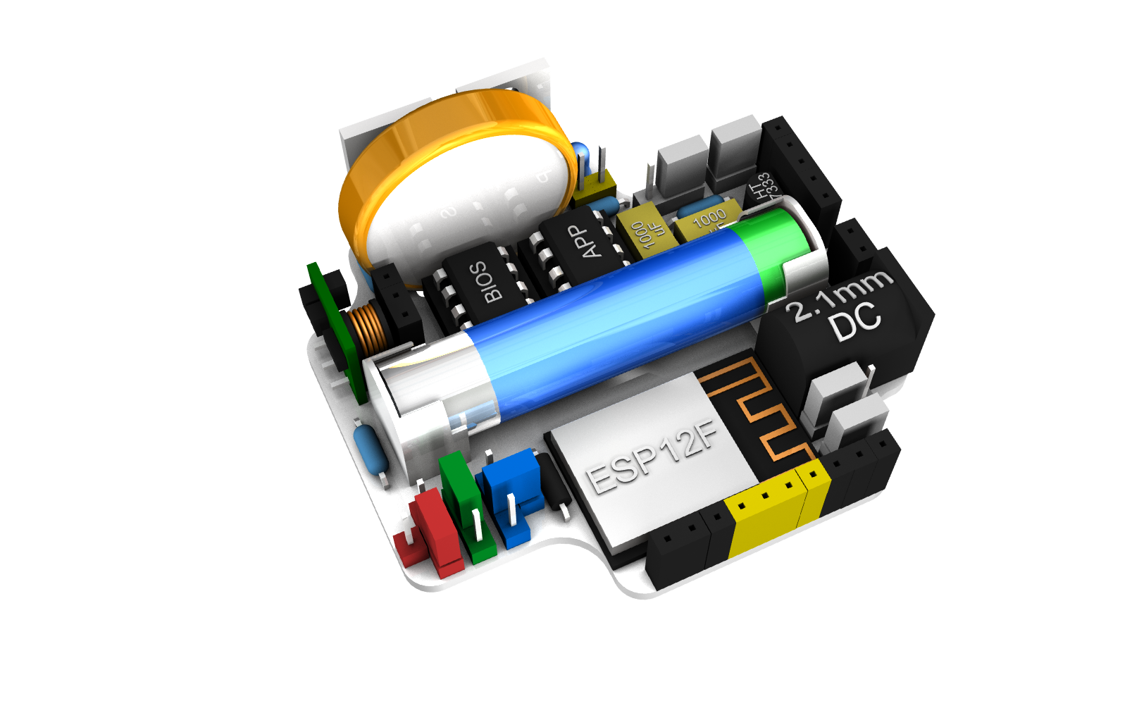
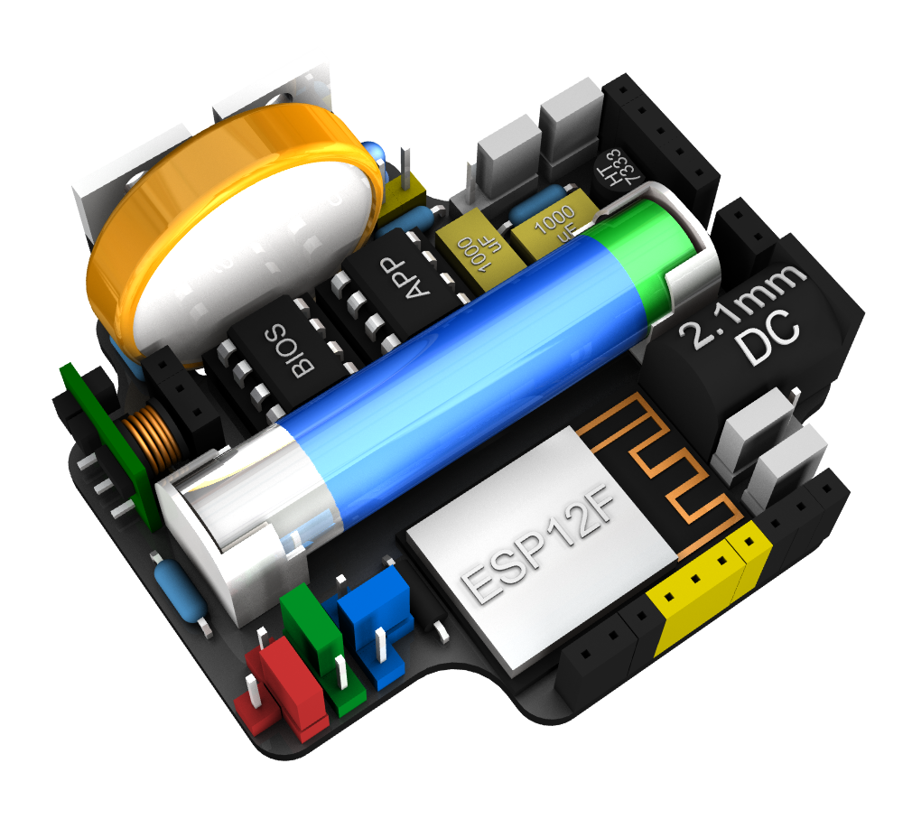
Coloured render
I have been working out if I can style this with matching colours and purchasing parts appropriately. This is the colouring I have come up with so far.
Colours aren’t consistent
I have started receiving some parts, luckily the male pin headers and jumpers have both arrived. This has given me an indication of what colours would be stable at scale. The yellow jumpers are actually brown, whereas all the other colours are fairly solid.

Update: I tried a second batch of yellow jumpers to see if they could ever be an option. I asked the seller and posted the above photo to check whether the jumpers were actually yellow – their answer was “I would say kind of like dark yellow.” This is what arrived:

So yellow jumpers aren’t an option as it’s too unreliable, and yellow headers are possibly the same I may have got lucky getting actual yellow.
So I have changed colours around on the board so that I can work around this. I have changed the serial sockets and the reset pins over to yellow as they will be used together and don’t require a jumper. I’m purposely not using female white headers as they tend to be inconsistent as greys or off white or creams. Try choosing a white paint! However the male pin headers and jumpers seem pretty good so I might be able to use them to make the board less dark.
Now I need to see if the yellow female headers arrive in brown. If so then I need to swap again but I’ll probably change it to blue to go with branding.
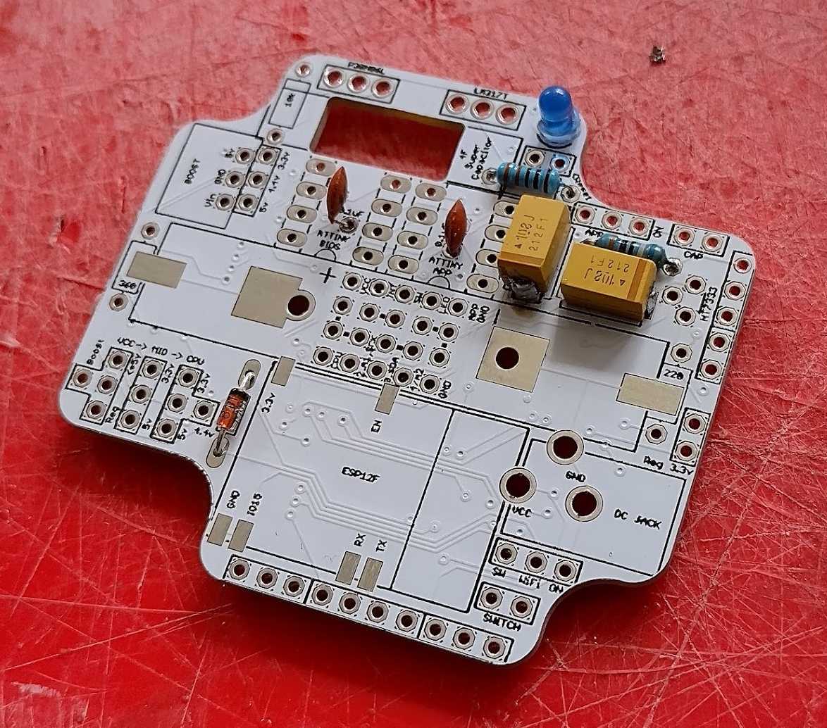
PCBs have arrived

The first run of the PCBs have made their way here from the manufacturers and the quality is top notch. The sizing is spot on, the cutouts are big enough, everything looks ok. As this is the first run I have noticed a few things, most of which were expected:
- The EN pad for the ESP12F is very close to a centre pin hole which will need to be moved in slightly
- The WiFi antenna may interfere with runs underneath it, they can be routed around that area
- The ceramic capacitors I have don’t fit in the cutout of the IC holders – I have ordered smaller multilayer ones.
- The DC jack pins are too large. I measured only one which happened to be the smallest whereas the others are too wide. The recommendation is to use slots which I avoided for this initial run.
- The MOSFET & regulator chips at the top take a little bit of force to get through the holes, but I think this is acceptable.
- The writing is very tiny, might need to be bigger in some places (eg. the ‘reset’ label) & I noticed they paint over the vias so I can put text over those.
Overall nothing bad enough to stop a few test boards from happening, but it’ll need another round to get closer to commercial grade. So once a test can be built to confirm the circuitry is correct then the adjustments will be made with another run to be manufactured.
To be fair with all the 3d modelling and double/triple checking it is spot on what I was working with virtually, which has saved many revisions and delays.
Test assembly
I have started a trial assembly of the board with components that I have, just so I can get it going and see if all the connections are right. It also allows me to record which components need to be soldered in which order. It’s not complete just yet but here’s some photos of each stage.


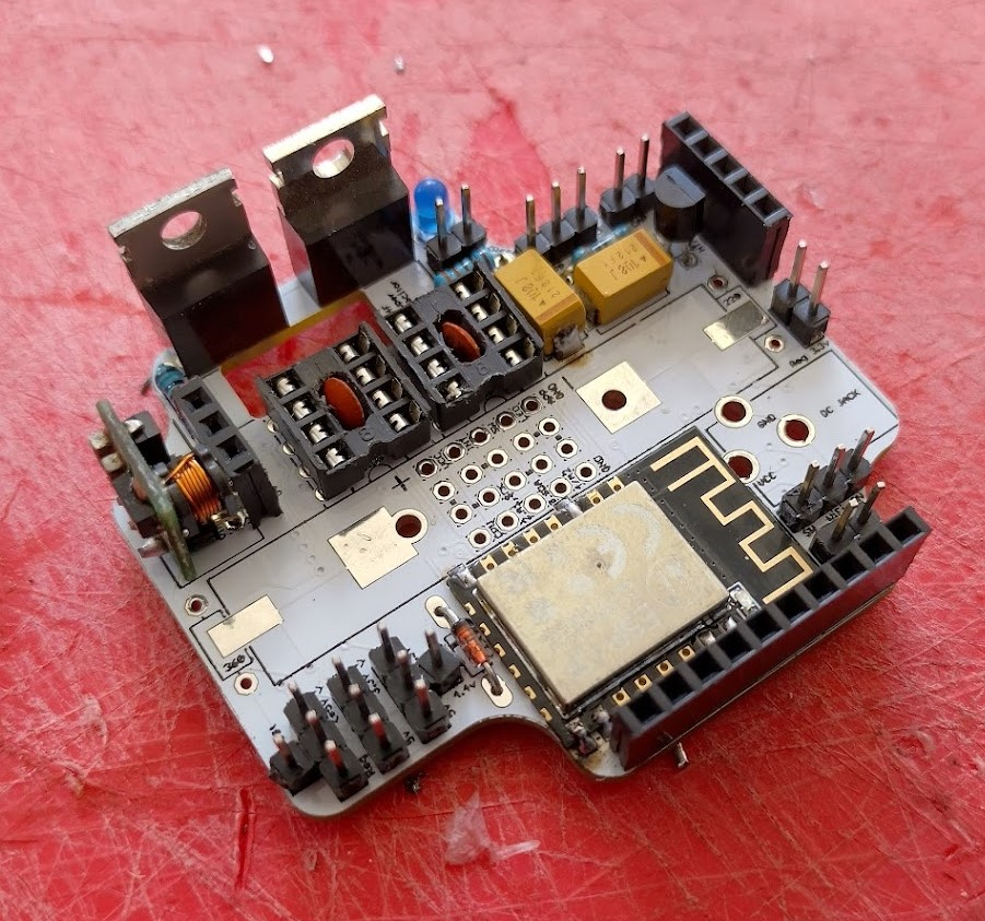
A few notes for this round:
- The holes for the MOSFET and regulator need to be the tiniest bit bigger but I have no room there so I have to come up with an interesting solution for that.
- The boost headers are hard to solder straight
- You might notice the IC sockets – I had to cut out a portion of the middle to fit the decoupling capacitor, but this shouldn’t be an issue with the new capacitors
- The DC jack pins need to be ground down – I haven’t added it yet.
- It is very difficult to solder – it requires a very fine tip and a steady hand, both of which I don’t have.
It’s getting there. Tomorrow I hope to have a completed version so that I can start testing and see if the wiring is at least ok. Then I can refine it and send off another order to get printed.
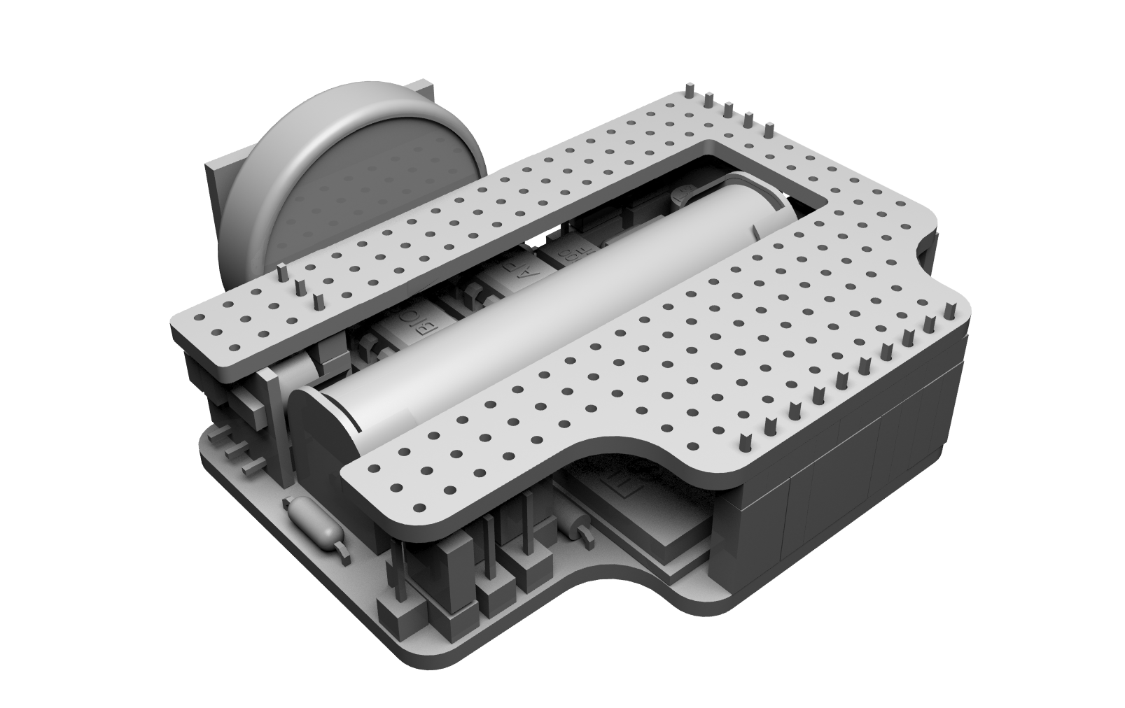
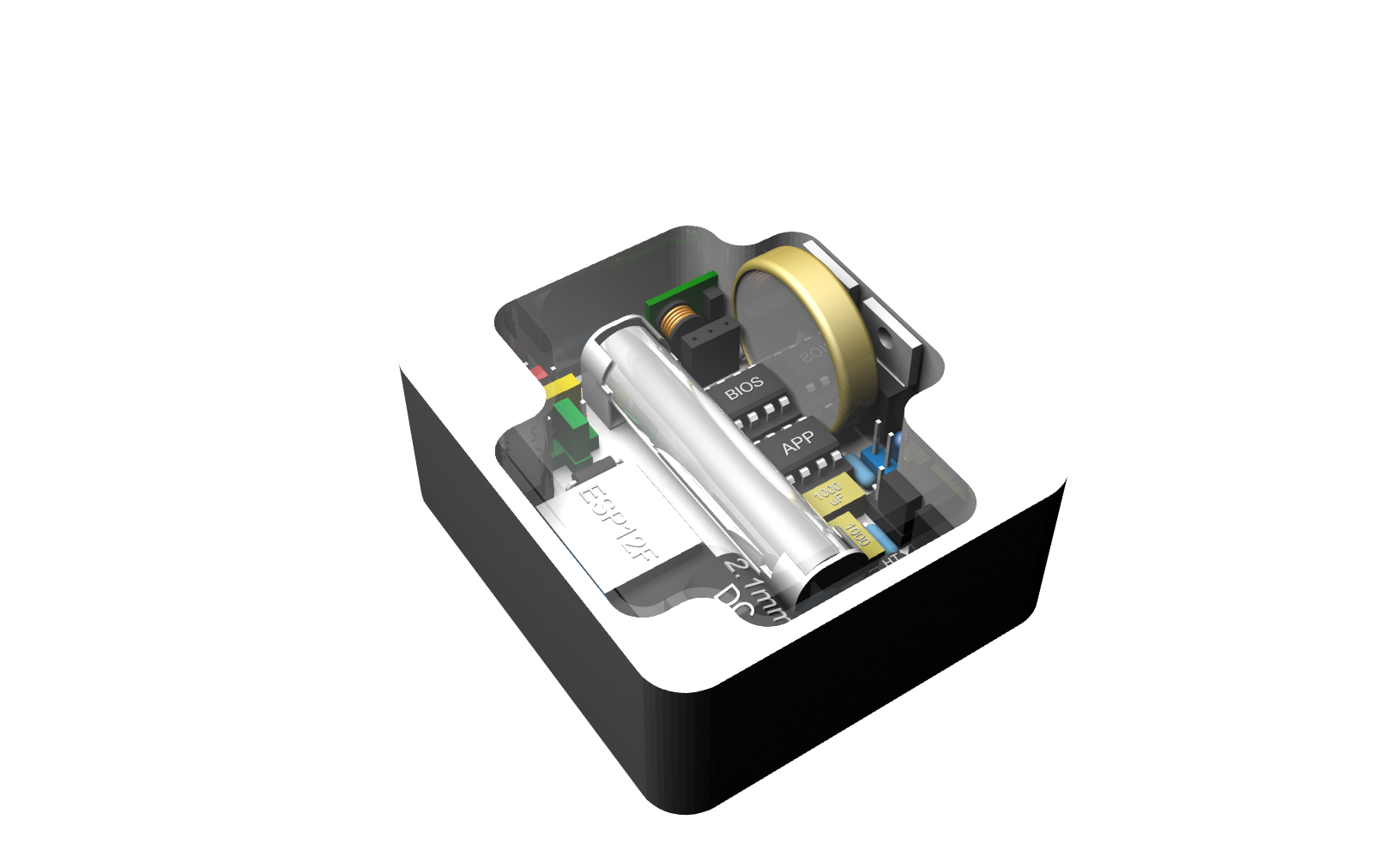
The good news is that it all fits in the enclosure exactly as planned!
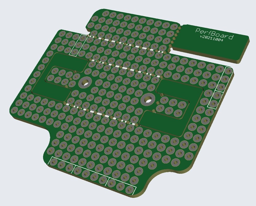
The bad news is the perfboard I designed doesn’t work as well as I had hoped. It’ll do for my purposes as I can cut it cleaner, but I need to find a nicer way to snap the pieces off as that is the whole purpose of it.

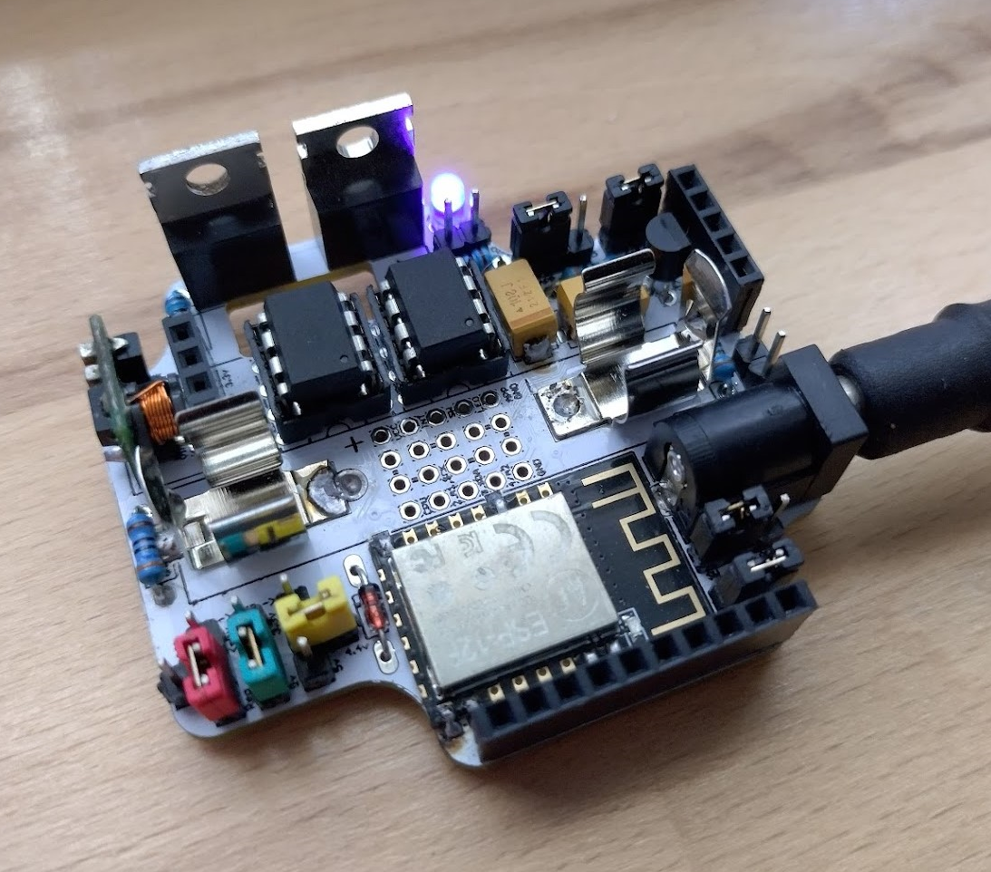
Mostly assembled
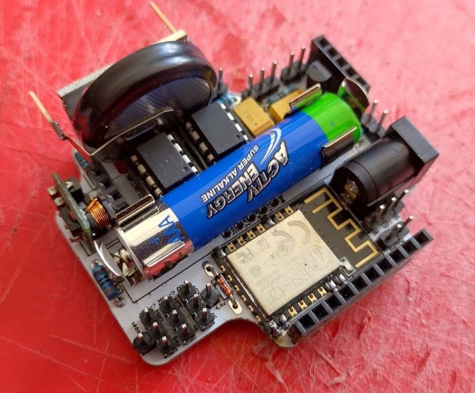
I have now got 99% of it assembled for testing purposes. This has really highlighted the difficulty in soldering and the different order things should be soldered in – some of which surprised me. However with a bit of jigging I should be able to test the actual circuitry on this to see if I actually got that part right.
Testing
I have managed to run a few tests with it so far and things are looking ok. Here’s what I have discovered:
- The bios will only respond if I power it directly from the FTDI, the CPU jumper is removed (blue), and the app chip is not present.
- The voltage jumpers seem to be ok for everything battery related, I haven’t checked the DC regulator yet.
- The MOSFET works, as do the jumpers that are marked as SW.
- I have been unable to get it to contact the website yet – this is difficult to debug due to the serial trickery.
- I might change the board to black to give it a more unified look.
I think most of the issues I’m facing will be solved with a DC power solution and/or the large capacitor. But for the most part all the connections seem to be right.
Success!
I soldered together a DC jack and have it powered from a 12v supply which has let me test it all out and it’s successfully contacting the website with some data. Here’s some notes:
- The 12v supply is far too high for it due to the heat it’s creating but good enough for testing. I think the ideal plugpack would be around 7v, I think it could go as low as 6.5v though to reduce wasted heat, if the circuit was to need high current 5v.
- The 3.3v regulator trick I tried doesn’t work – the regulator ends up combining the two resistor values together to create around 2.5v instead so I’ll change this to a 3 pin swapper
- The battery isn’t good enough to get past the power blip of the wifi, it needs the capacitor which hasn’t arrived yet.
- The ESP12F was set at its default of 115200 as I had forgot, however it was very easy to change in-circuit which is a huge plus.
- The APP chip was programmed but I forgot to run the init function. Once that was switched on it all came to life.
- The wifi doesn’t seem to be interfering with the runs beneath it, so I can leave the central mini perfboard in place for now.
This confirms the wiring is all good which is a huge relief. So next step is to adjust the board to solve the issues I had while soldering, run a few more test apps such as the oled screen and gps to make sure all of that is ok, then get some more boards printed and on their way. It’s going to be a busy weekend.
Adjustments for the next round
I have spent the day solving all of the little issues that were found while assembling this first batch. Mostly minor except for the regulator.

Here’s a list of what’s changed just for interest:
- increased centre holes to fit toothpick, matchstick to prevent solder from filling and suit planned screw size
- moved top and bottom corners in a tiny amount to give a bit of buffer from the sides of the enclosure
- moved the left battery clip out a bit
- moved the wifi jumper down to improve clearance from the dc jack
- added + labelling to the led
- moved reset label as it’s barely readable
- moved top wifi pads down to increase clearance
- moved bottom border up 1 notch to improve clearance
- increased hole size for mosfet & regulator
- changed all labels to at least 0.8 size
- added third pin for regulator to function correctly at 3.3v
- routed all traces away from the ESP12F antenna area just incase
- increased hole sizes for DC jack.
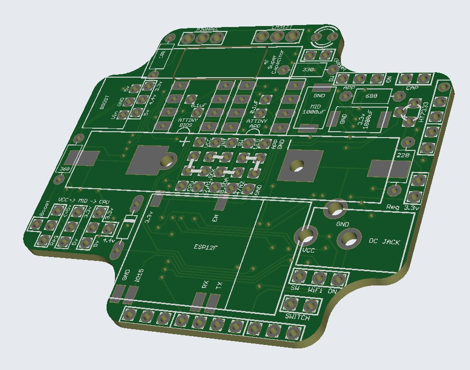
I have stared at it enough and want to get this second revision here as soon as I can so I have sent this off to manufacture, along with a few sub boards for GPS, OLED, and ESP32Cam. Here’s the gerber along with a 3d view done in KiCad as the online version isn’t working at the moment.
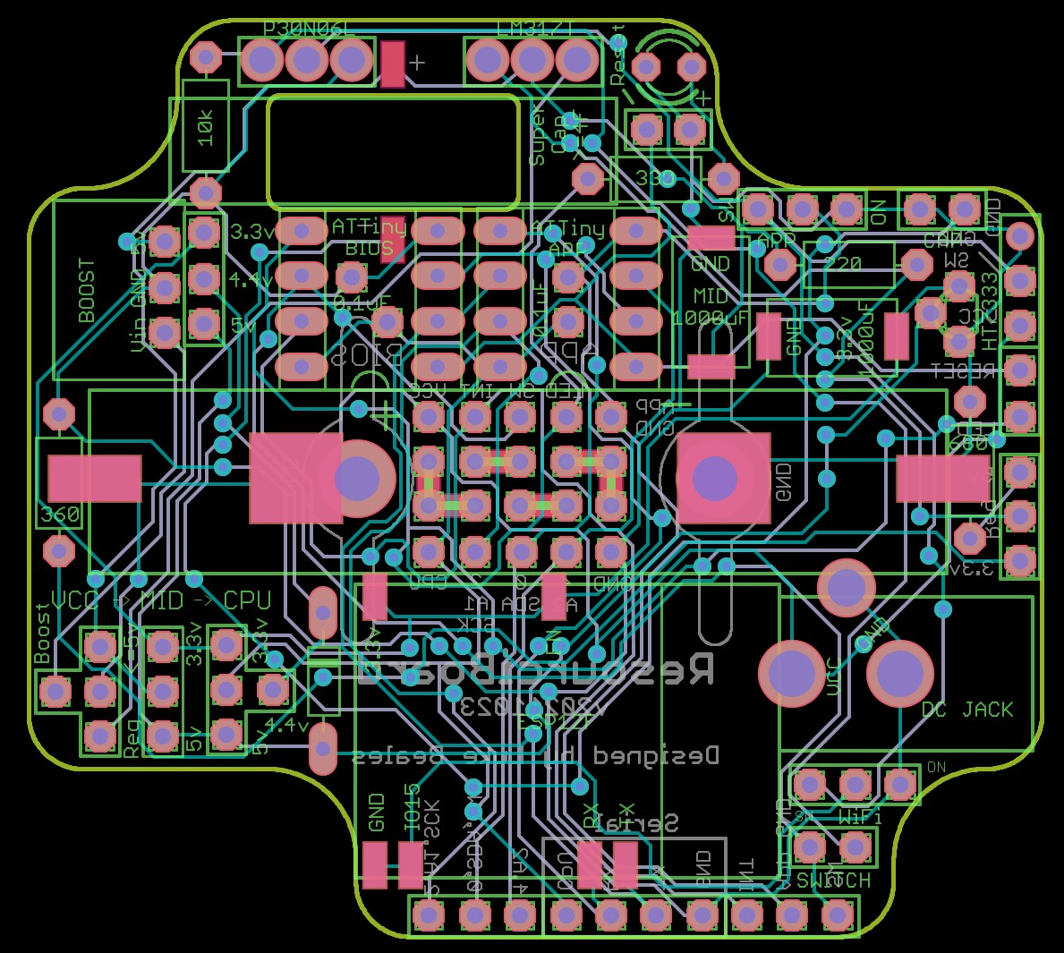
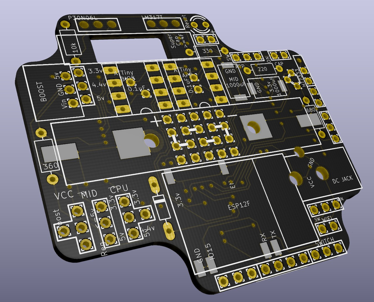
Now it’s a wait and see for when these will arrive.