I am building a compact device with WiFi based off an earlier successful prototype, which if it could run off a commonly available battery it would vastly improve its uses.
Due to constraints of the enclosure, the biggest battery that is commonly available is the AAA.
Let’s see if we can get this to all work from an AAA sized battery, or smaller!

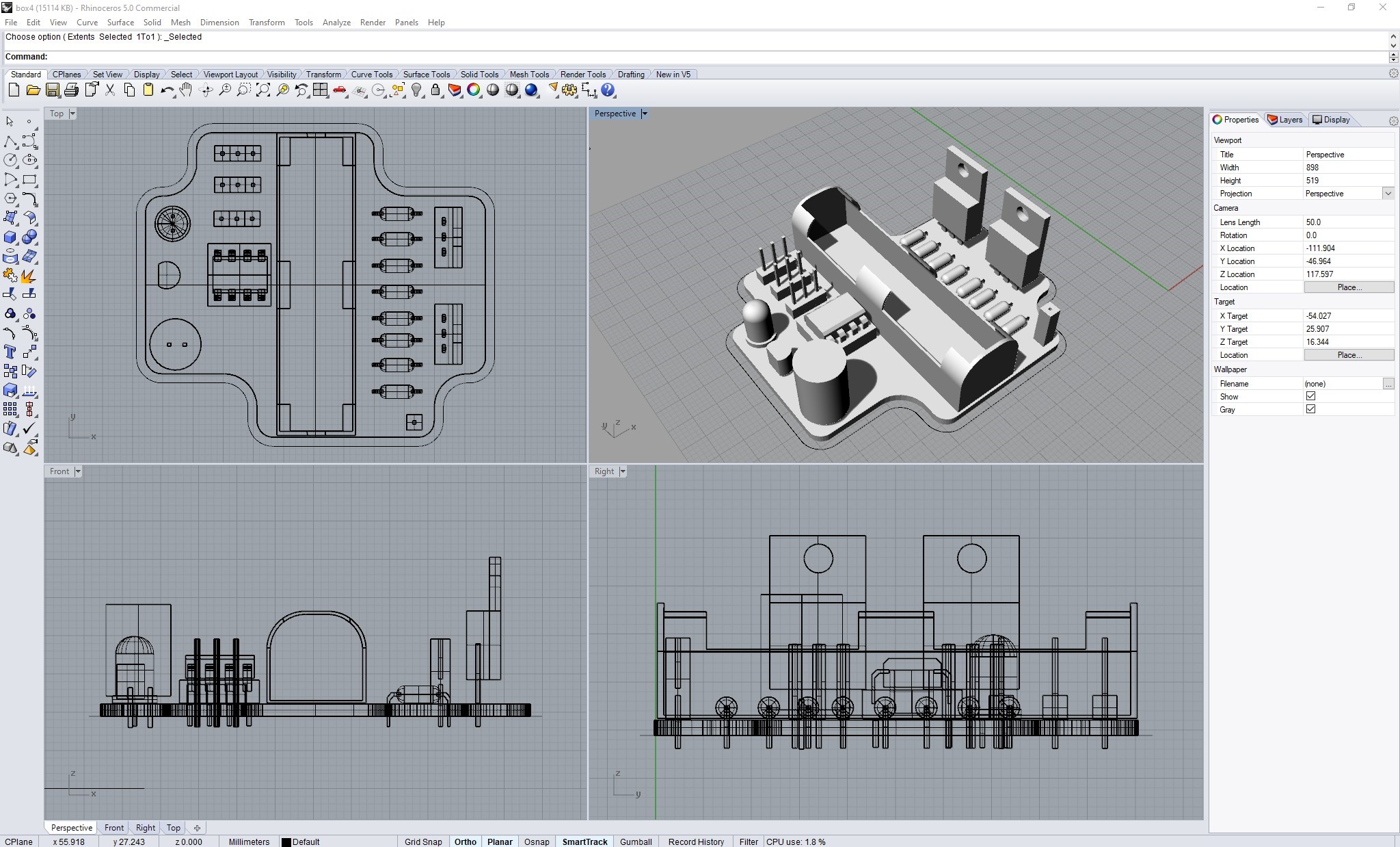
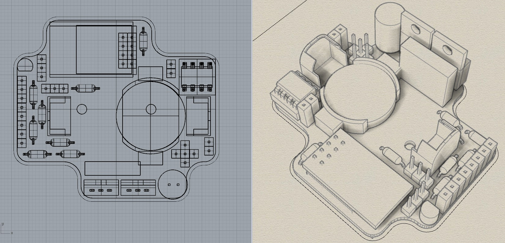
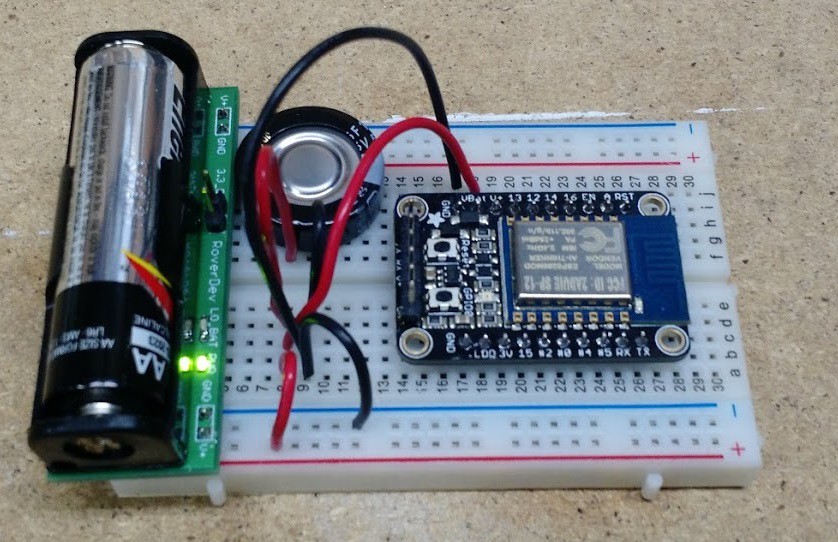
This is the general board in an early stage with the AAA as planned, but untested.
Battery woes
At this point I wanted to see how long the AAA would last with the hardware so I would have some idea of its future uses.
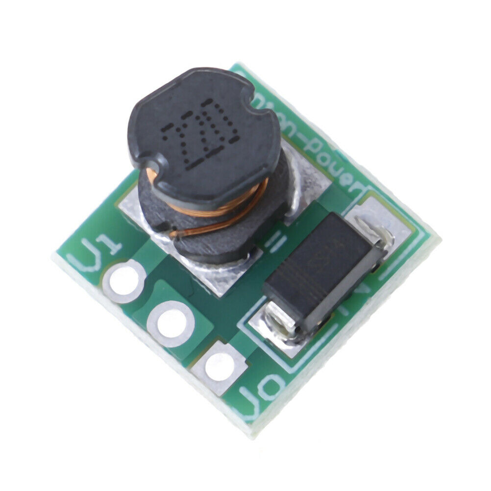
Using one battery requires a step up converter to bring the 1.5v of the battery up to 3.3v that the ATTiny85 and ESP12F/8266 require. I had a 5v step up board so I decided to try it with the regulator to see how long it would last, but it wasn’t good.
Each time the ESP12F powered up, the ATTiny85 would reset. I tried a number of things from multiple capacitors, more batteries, etc. The multiple batteries gave some success but it couldn’t make a valid web request, and the batteries wouldn’t fit in the enclosure. I had a similar issue when I tried to run this from USB in the beginning – the USB port just couldn’t provide the regulator with enough current.
Also I tested the 5v step up and 3.3v regulator combination which managed to last around 24 hours of the ATTiny85 running for 20s each minute. This isn’t enough.
So I have decided at this time that the battery mode will have to bypass the regulator, and use a 3.3v step up board instead. This limits the subboard possibilities but it’ll have to do, and hopefully be vastly more efficient.
If this doesn’t test well then I have to look for another battery – either 2 x AAAA size, or CR2025/CR2032 coin cells. These aren’t as common, but a positive side effect will be that both options can allow for solid subboards above them.
Battery Solutions
After a lot of research it seems I should be able to run this off the AAA as planned without the regulator in play. With a possible lithium (LIR2032) coin cell option I have found I can place it in the same position as the AAA cell, so it’s sitting there until I work out more.
The coin cell idea comes from this youtube video where it requires a tiny HT7333 3.3v regulator which of course takes up more space, it’s available in a transistor sized package so that’s doable.
More trial and error
I did a number of trials with my test board and capacitors, along with an LIR2032 battery and 5v step up converter. This wasn’t quite enough to get a successful photo uploaded from an esp32cam. Even adding multiple capacitors and such. However earlier on I discovered this video:
This demonstrates the ability to power a straight ESP32 off of an LIR2450. The only changes were a tiny 3.3v low dropout regulator, and a massive 1000uF capacitor. So this shows I should be able to power all of this off of a battery at least but not sure of the ESP32cam. It will all depend if the new 1000uF capacitor is enough with the 5v step up board.
If that combination isn’t great then it will basically be a point of ruling out the 5v step up almost, which then allows the 3.3v step up to be soldered to the board directly.
Coin cells and current
I ended up trying a very similar arrangement as the above video without much success. I couldn’t get the wifi to boot up successfully with my coin cells. The issue I believe is the LIR2032 sized batteries. These only contain about 40mA, and the sustained current they can provide is too low at around 60mA. This is far below the 80mA the esp32 requires, and much lower than the 100mA the larger LIR2450 batteries can provide in the video above. So these coin cells have been ruled out.
AAA sized 10440 batteries
I am having a lot of success with the 10440 sized 3.6v batteries with a large capacitor and a HT7333 low dropout regulator, almost the identical setup to the video.
This has allowed the esp32 to start up for about 10s every minute, lasting for a number of hours. The total cycles seems to be around 270 web requests. Success!
I have yet to receive the 3.3v step up boards or the proper capacitors, so until then this is the best I can do but once they arrive I hope it provides better efficiency, and the ability to use a standard AAA.
3.3v step up boards
These absurdly tiny boards finally arrived a few days ago, so I have been frantically testing but no success yet. I tried adding multiple batteries, multiple step up boards in parallel, big capacitors. There’s too much voltage drop. I even built a dedicated 1.5v power supply which still couldn’t handle it. I think the ESP32 is in permanent boot mode so it just sucks the current from anywhere it can find it. An esp8266 didn’t have any different outcome.
More research has determined this thing needs a massive capacitor for the extreme current draw at the beginning just to survive the boot. Maybe that needs to be bigger when boosting from 1.5v? I’ll see once the capacitors arrive. I know it’s possible to do this – just how?
Brilliant little boards though for anyone who needs higher voltage from a AAA – just not a lot of current for these!
Trials and failures
I have been experimenting with any and every way to get an ESP32 to boot off of a AAA battery with no luck.

What is puzzling me is the success of the previous test with a 3.7v 10440 battery and a LDO regulator. There are only two results I have found from searching – one said they had used a led driver circuit which provides an immense amount of current but heats up the battery. There was no circuit provided. The other said to connect the CH pin of the ESP32. I had that connected on a previous chip but I have broken it in my testing. So at some stage I’ll wire up that pin on this board and see how it goes. But I feel like I’m missing something obvious…
It’s all about the current
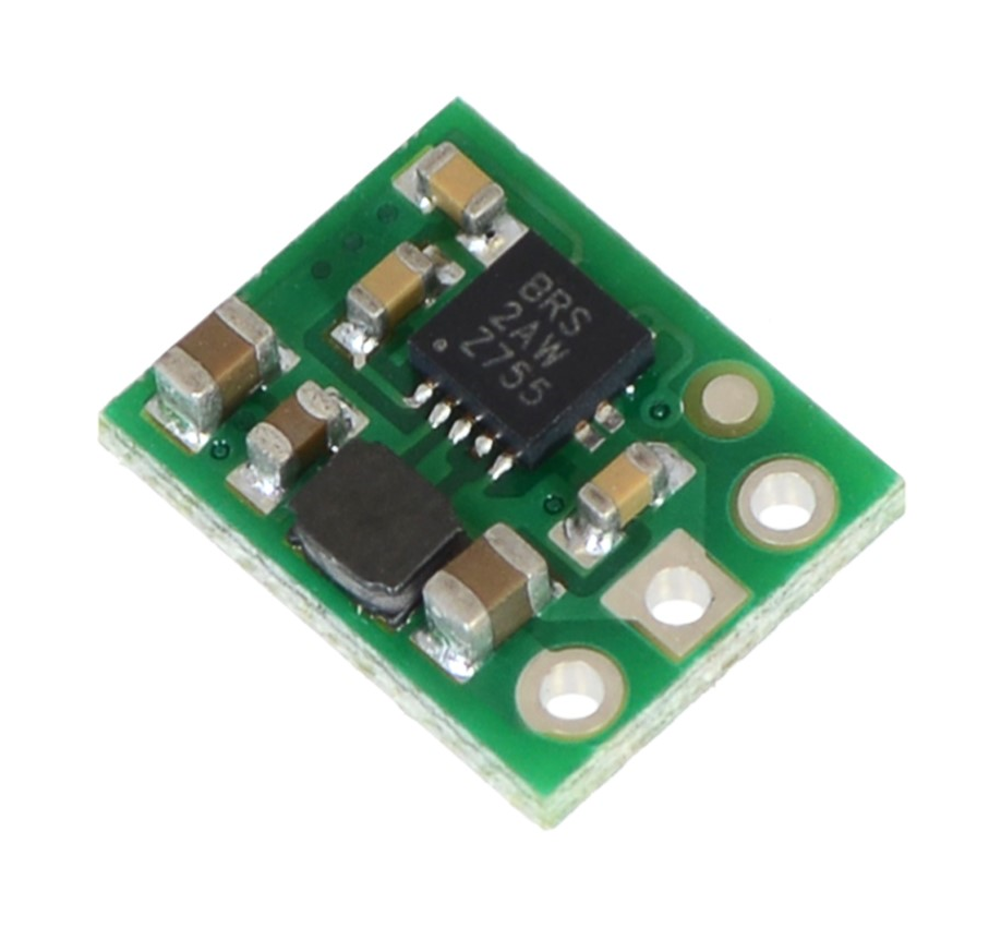
A bit of time has passed and a few things have happened. I researched a lot and discovered there’s a Texas Instruments TPS61xxx chip that is more efficient which a company named Pololu make step up boards using it. So I got a few of those ordered.
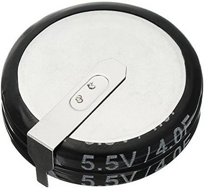
I also got handed a super capacitor to try. This is a 4F which is massive and takes forever to charge. I didn’t have much luck with it, but I did have ever increasing hope when plugging multiple small capacitors together as the ESP seemed to boot a little further each time. So I knew I was on the right track.
I then stumbled upon a product that was made many years ago called a BooStick made by CaptMcAllister. It is no-longer made, but it utilises the same chips in the new regulators I have ordered, and the bonus is the creator has an image on there which depicts exactly what I am trying to achieve.
I got in contact with CaptMcAllister who informed me the capacitor he used was 1F, and it required charging before the ESP could be plugged in. Perfect! I had tried this method but I realised the BooStick contained a Tantalum capacitor similar to what I had on order, but about 1/5 the size. So I had to wait some more.
The capacitors finally arrived! I soldered them and the new regulator boards and tried a cold boot. All good, the ESP threw things on the serial port but unclear. Still better than what I had achieved previously. So I plugged in the super capacitor and let it charge.
Success! The ESP boots. It doesn’t last long, somewhere between 7 to 12 seconds and seems to draw around 70mA continuously, but it works!
I am going to try a few different combinations of things to see if I can get it to last longer, but it means a common battery is back in the race! And it may even work off the old regulators which would reduce costs a bit…
5v to the rescue
The board that this will be part of will require some 5v parts to interface with 3.3v (the ESP). So I had a theory to boost everything up to 5v where the capacitors will sit, and then regulate down to 3.3v where the wifi will sit. This should then be the best of both worlds and in my mind allows the capacitor to charge more and allows for a larger voltage drop before it will fail.
It was a success! I got 43 seconds of ESP32 usage before it failed, however it required a long charge time in the manner of about 5 minutes. And the ESP did reset right at the start, so a second smaller capacitor is probably needed on the ESP side.

So this will be the way I move forward. It’s now just a matter of which regulator to use, and what combination of capacitors to get the best charge time.
More trials and errors
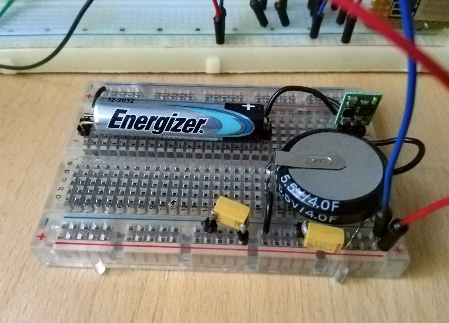
Now that I had success, I decided to try different batteries to see how long they lasted, etc. and stumbled upon an interesting issue. I attempted to charge the capacitor with the energiser and the high cost board knowing it’s more efficient, and only got 10 – 15 seconds of runtime from it. This didn’t match what I saw previously. So I then tried a much cheaper battery and it worked slightly better but still not great. A 10440 worked good, but not amazing. It stayed on forever but the charge time wasn’t spectactular.
Out of interest I swapped back in the cheaper boards, just the 5v one this time which I believe is called a charge pump. With this in, everything ran perfectly. The capacitor charged fast, and the wifi stayed on for a long time – minutes – no matter which battery I used. I could watch the capacitor very slowly drain away. I then thought maybe it’s the ESP12 because it’s not actually connecting to wifi yet. So I connected it to wifi and everything suddenly went stable. The capacitor would jump between different voltages but never trickle down. This is the answer!
Making it work alongside an ATTiny85
With that worked out, it is now over to trying to get it the ESP12 to work within the whole board assembly. I hit a snag where it kept resetting but clearly it’s the ATTiny85 I’m using. So I moved the Attiny to 5v and the ESP to 3.3v – problem solved! I now have a battery powered ATTiny85 wifi device sending values up to a web server each minute.

This could probably be solved with the low voltage ATTiny85-10PU as I think that’s the only issue – the voltage is dipping too much, but they’re incredibly hard to source.
The only thing left to try is to adjust the capacitors to see if I can get them a bit smaller for quicker charging.
Success finally.
Reducing the capacitors
Enough super capacitors have arrived and I have moved things around a bit on the ResourciBoard so it’s time for more testing.


The board is powering a simple monitoring app which pushes pin states up to the internet every minute, similar code to what was running in the last tests. Here’s what I have found:
- Using a Lithium Ion 10440 with no supercapacitors:
- It works and makes a successful web request
- Using a Lithium Ion 10440 and 4.0 of capacitors it:
- Charges within seconds.
- With all 3 chips it keeps a steady 5v.
- This does a successful web request.
- Using a standard AAA and about 1.5F of capacitors it fails:
- Charges rapidly – unsure if this is due to it being in parallel
- With just the BIOS chip enabled and running, the voltage drops to 4.4v during the on cycle.
- With the BIOS and the APP chips, it drops to 4.25v
- With the BIOS, APP, and ESP12F, it drops to 3.1v which is below the regulator.
- Putting in the previous 4.0F capacitor it does this:
- Charges extremely slow, about 5 minutes
- With the BIOS chip in its on state, it drops to 4.35v
- With the BIOS and APP chips, drops to 4.3v
- With BIOS, APP, and ESP12F it drops to 3.19v
- There seems to be a big 0.4v or so drop about 5 seconds into the ON phase, caused by the ESP12F.
The 0.4v drop lines up with after it has connected to WiFi, but it then makes a TCP/IP connection to the web server. Previously I was keeping the WiFi settings in there, but I have added a line to clear it each connect. This might be drawing too much power. Or it’s the two ATTiny85’s.
Need more power
I have spent a lot of time trying to reduce power everywhere I can as I think it’s the two chips preventing it from working. So I have written super low power delays in the app chip to attempt to claw back some precious milliamps. This has had a bit of success in that I got it making a few successful web requests off a standard battery.

This gives me a decent idea of what the end device might look like. I now know I require a giant capacitor of 4F or maybe even larger if I can find one.
There is an odd issue though where the APP ATTiny85 is resetting if the battery isn’t almost brand new. This might possibly be solved by the lower power ATTiny85-10PU but I am trying to avoid those just yet as they are far more difficult to source. The BIOS chip does work however. So something is amiss. More trial and error.
A few theories
I have been thinking about the above issue where it was working perfectly earlier. The only thing I have changed is I am now starting up an ATTiny85 at the same time as the ESP12. I think that might be what is causing things to not work 100% as well as they did previously.
I also discovered these ESP12F’s automatically reconnect to the wifi on startup. There is newer firmware that solves this but I am trying to use as many standad parts and code as I can. So I have added a check to detect if it has connected already and not to connect again as this causes a double dip in power.
So how to fix the ATTiny85 from starting at the same time? I could add another large capacitor on the 5v rail which might solve it, or a capacitor in series with the APP chips VCC. Or I may have to come up with a delay circuit. Looks like I can’t send this board off to print just yet.
A possible answer to the restart issues
I believe this might be narrowed down to the watchdog timer within the Attiny85. It’s generally a good thing to have as it makes sure the chip resets when it hasn’t done anything for a while – but in some cases you might have an external reset anyway, or it’s only designed to run for a few seconds or minutes at a time. When this watchdog is disabled it solves so many odd gremlins that have appeared. So if you’re having a chip that’s acting inconsistent, take a look at what it does for the watchdog monitoring.