This is Part 1, If you would like to skip to Part two click here, or Part 3 can be found by clicking here.
The theory is to take the rough concept that I designed almost a decade ago, and bring it in to a modern world now that WiFi is cheap. The requirements for this board are:
- This should be useable on its own as a single board so that the costs are low.
- Accommodate pluggable boards on top. The headers should be placed to support a board with/of:
- a couple of ICs
- an RFID reader
- GPS
- ESP32cam module
- DIY Veroboard
- It should allow for (limited) functionality on a common battery, for a decent amount of time
- Allow for either the ESP12F or ESP8266 – whichever can be aquired at the time
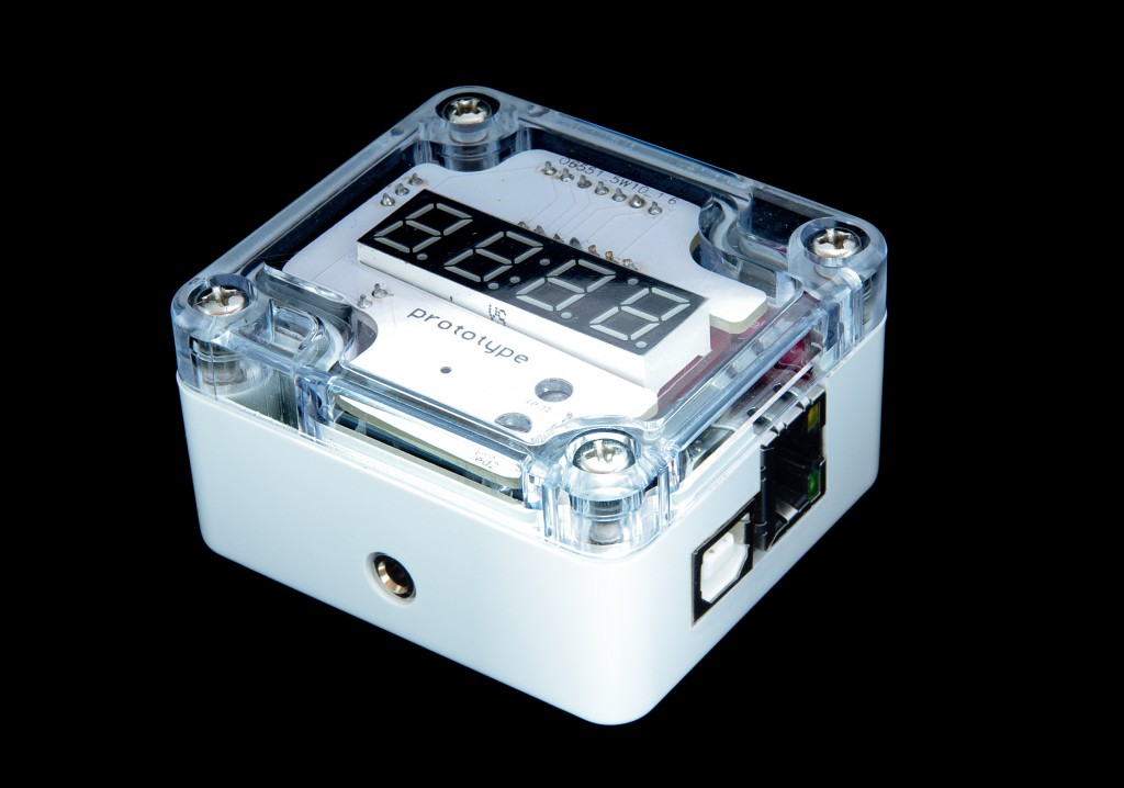
- It should fit in the standard original enclosure, with the ability to easily allow plugs for power/data/etc.
Time to see if I can get it to fit.
Initial arrangement
I spent a lot of time thinking how to get all the pins outside of the enclosure in an easy DIY way. I liked headphone and DC jacks as they are round, but have very limited connectors. Then I also liked the idea of serial ports as they have 9 pins which is the perfect amount and are standard, and the female serial port allows for no extra wiring should quick prototyping need to be done, but very hard to make the opening nicely without special tooling. I looked at more circular connectors and looked at PS2, and even airplane connectors.
In the end I decided it’s easier to just replace the top rather than drill holes in the sides. That way the top can be a flat perspex sheet and also millable. So this is where the connectors will be.
I dug up the old files from the original idea where I had modelled the entire enclosure, and got to work measuring and placing all the components where they would fit best.
The initial pieces
Due to the battery requirement I had to work out which of the more common batteries would fit, and how, and everything else would go around that. The most common battery is AA and it does fit, but takes up too much space. AAA is a bit smaller and contains more capacity than a button cell (which isn’t as common) so I tried for AAA first.
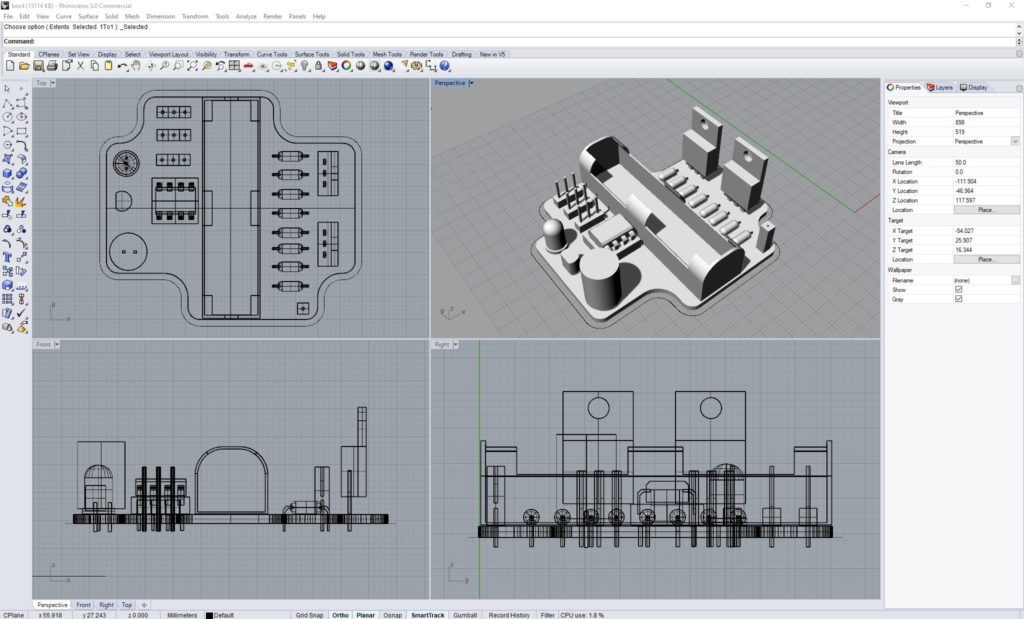
I ended up getting all the main components to fit nicely within the space available, but quickly this showed a few glaring issues.
The headers for the subboards aren’t tall enough to clear the battery, with the battery vertical this results in a separated subboard which isn’t good. This also prevents the ESP32cam from fitting nicely. So the battery will have to be turned around.
I also forgot a few major components such as WiFi, so back to the drawing board.
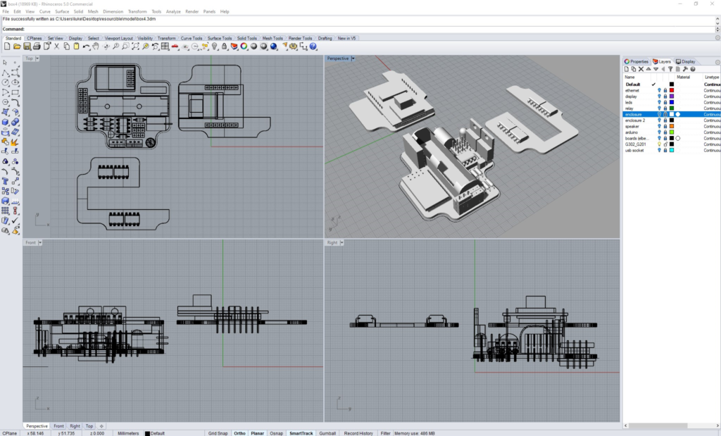
Getting better. Step up board (with differing dimensions) now has a place, daughterboard has a join which is significant and can hold two shift register sized ICs if needed. ESP32cam fits and straddles the battery.
Just have to get headers to be arranged nicely so a veroboard can be attached to this.
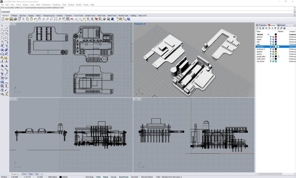
I realised others have used battery clips rather than a full plastic holder. This would allow the screw mounts of the enclosure to remain accessible while also reducing the space needed for the battery so I resized the battery holder, and offset it a little to allow for a larger area above for better subboards.
Also added headers for all inputs/outputs of the board to be passed through to the subboard in a more veroboard friendly manner.
This design is getting close as it also groups all the tall and unknown components in one spot to allow for changes in supplies.
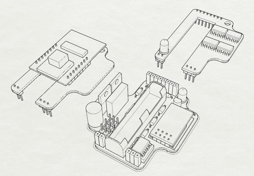
One of the main issues I have discovered with this is the LED is in the wrong spot – when it’s on for the ESP32cam it is blocked. So I will move it to a different position.
Who knew flashing a led would be so difficult
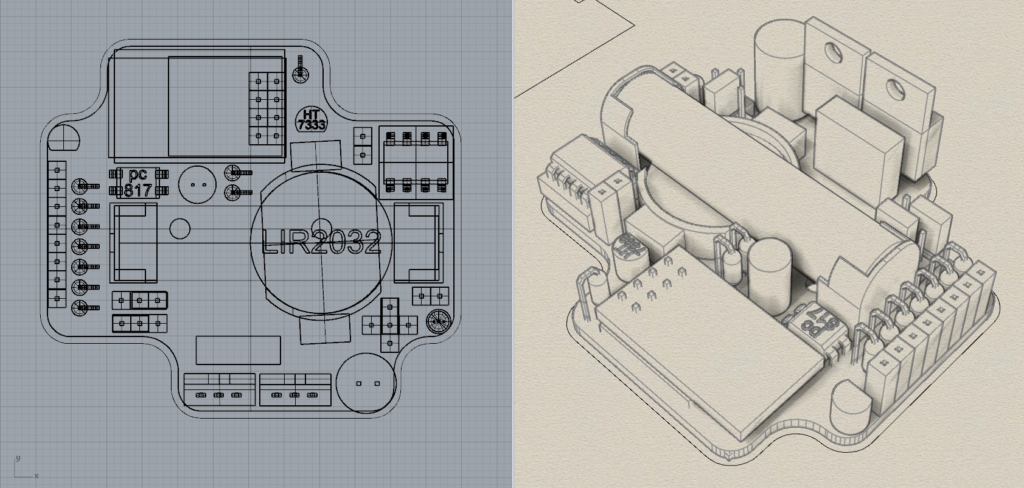
I am thinking the led uses up 20ma each time the ESP12F switches. That might be a tiny bit too much for the step up board, so my options there are to remove the led entirely or change the way it works. I have opted currently to see if I can get it to flash, meaning 20ma blips every couple of seconds. This can also be fed from the large capacitor to smooth things out even more. Turns out it isn’t easy to make a led flash but there seems to be a simple circuit using a PC817 optocoupler so I’m placing it on the board for now.
Building it in Eagle
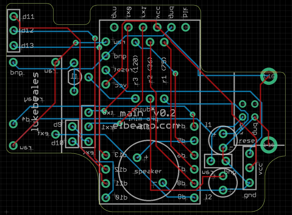
With parts on their way there isn’t much more rearranging until I can accurately measure them and test them, but I can start getting the rough board in to eagle in preparation of printing it. I imported the old elbeano board I designed years ago.
A few tips:
- Make sure the dimensions are in mm and not mil
- Outlines need to be a solid line. This is done by placing reference points (such as the circles) then drawing a consistent line all in one go.
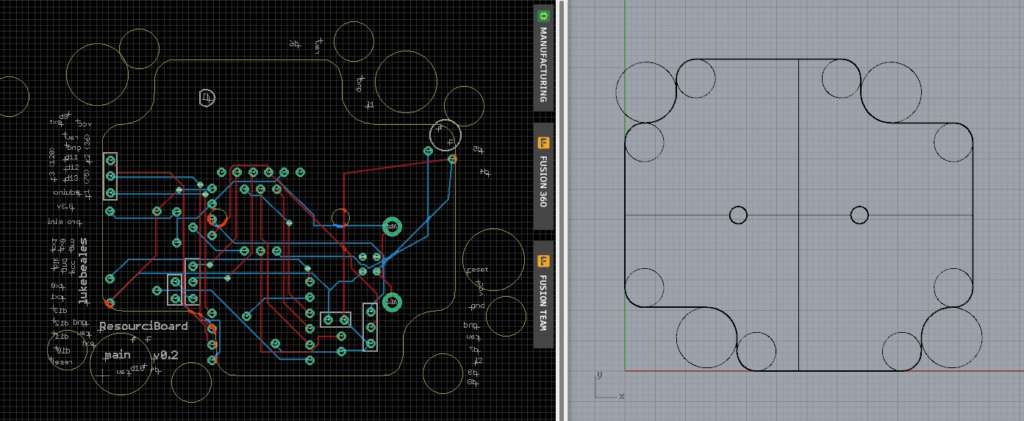
Flashing led power usage
The optocouplers arrived so I went straight to work testing the circuit. While it worked ok, it appears as though the timing was a set pattern which could be stretched to a degree. Great for basic led flashing but not what I wanted. Measuring the current (roughly) wasn’t promising either, where it would drain a battery fairly quick.
So over to a standard 555 circuit. I had made an on/off circuit before so I adjusted that to flick a led on about every 5 seconds and measured it. This was better, yielding in roughly 2 milliamps most of the time (and with a much smaller capacitor). I calculated this to a 1000mAh AAA battery which gave me 500 hours, or about 20 days. This was just the 555 timer drawing this. There are two ways to get it even better – use a second ATTiny85, or a CMOS 555!
The second Attiny85 was ruled out as I have no room on this board, and what if it corrups? I can’t solder it down. So Investigating the CMOS 555’s I discovered they use about 1/8th the standby power of a regular NE555. This should give me 160 days of led flashing which is perfect. I added a jumper to enable/disable it also so in cases of extreme battery usage the board will last much longer. The CMOS 555 is also available in SMD so I’ll give it a try.
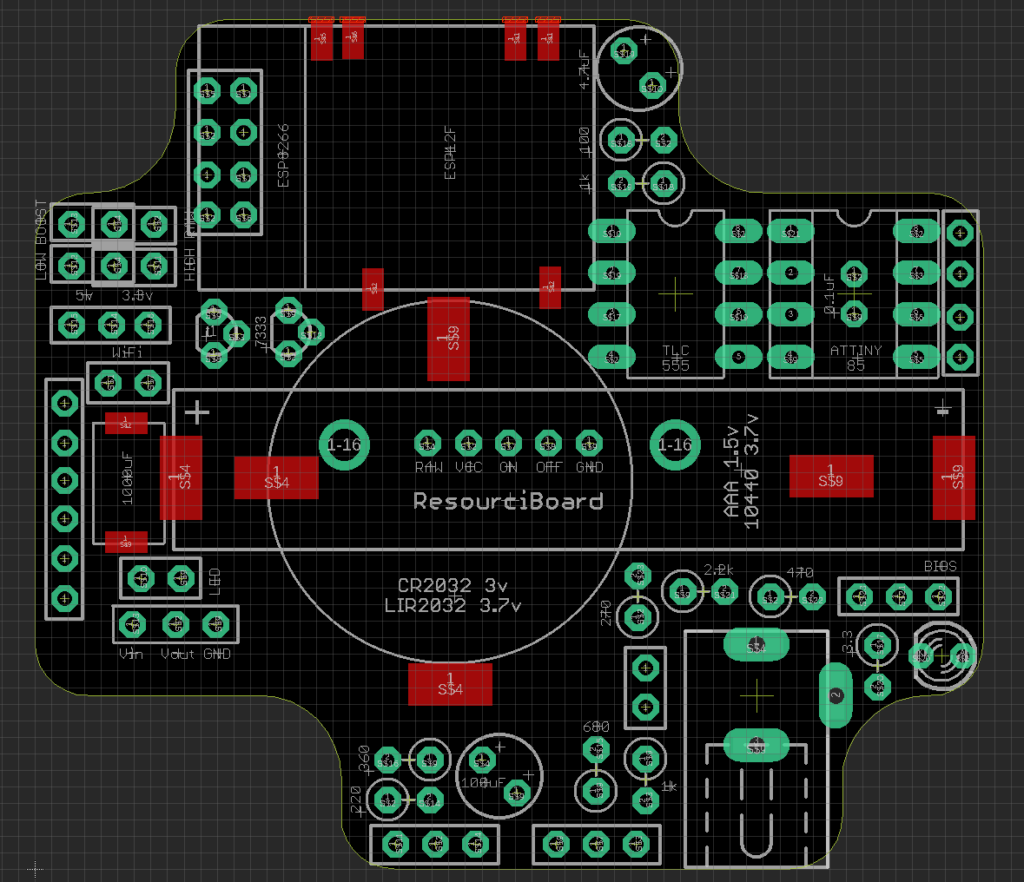
With this decided, it’s over to rearranging the board again. I have found I can hide some SMD parts under the AAA battery, and I might be able to get away with a smaller power rail capacitor now that I have discovered decoupling capacitors. So here is the latest board now with DC jack and convenient jumpers to set the power sources.
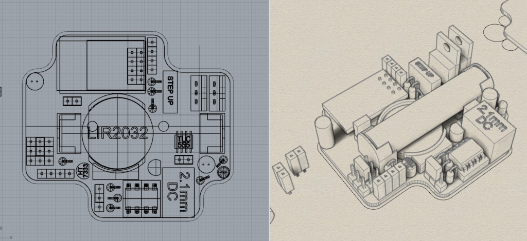
Aligning the regulator and MOSFET
The regulator gets fairly hot when dropping from 12v on a test board, so I’m not sure about it at the top right there. And if I sit them lower then I can squish them together a bit more.
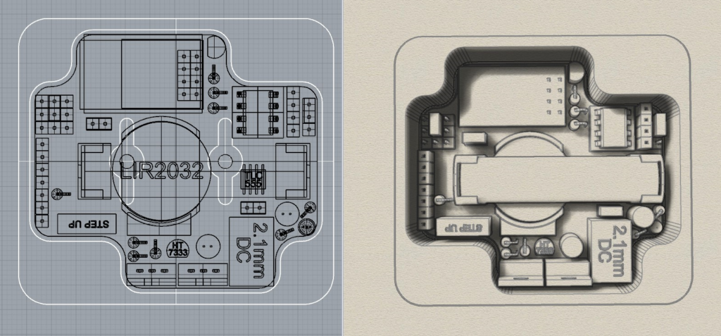
Ok another refinement done, most things are now sitting on the board with a little more testing needed. This makes all the headers veroboard friendly, and the mosfet and regulator are all aligned incase a heatsink is needed. Also only the right end needs to be trimmed from top boards to allow for easy bios jumper access and status led visibility.
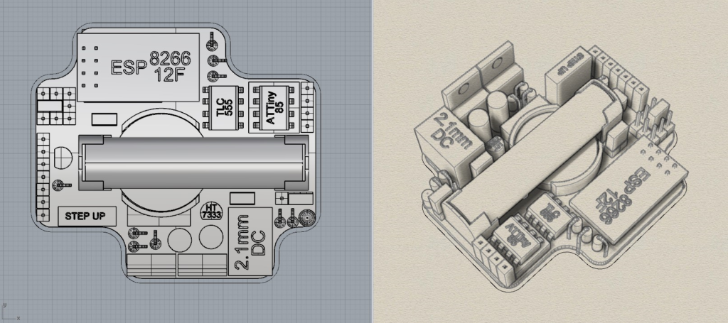
Testing the power supply
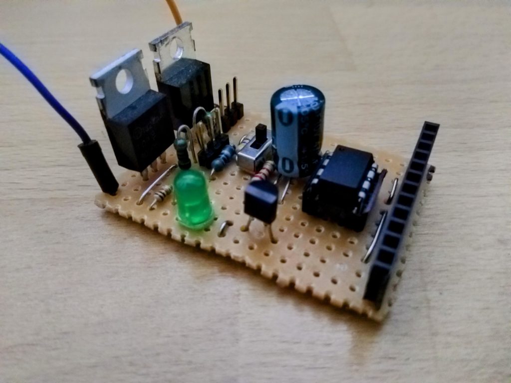
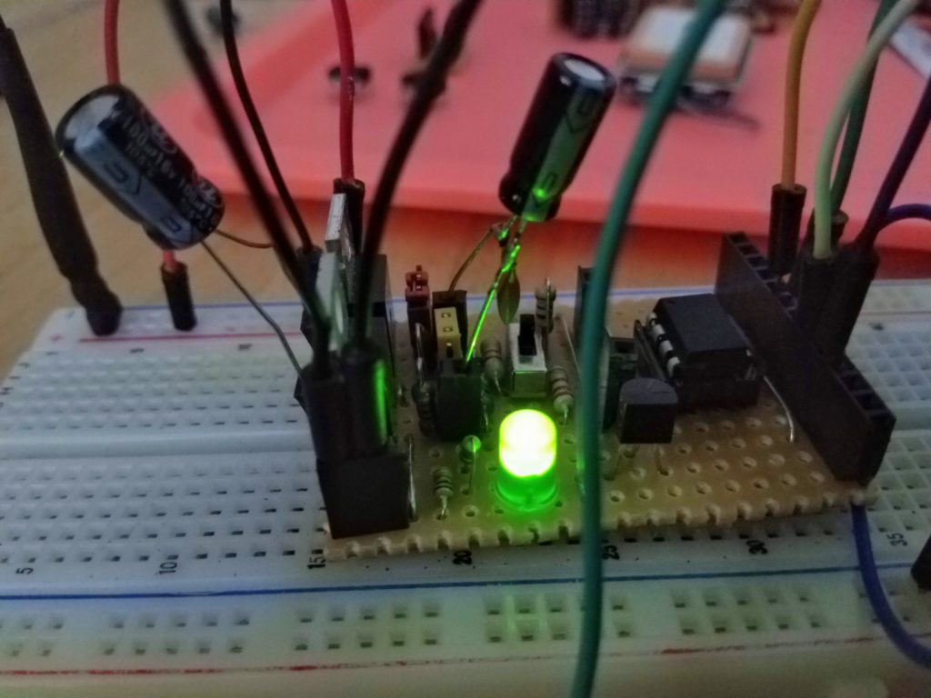
I looked at an old breadboard power supply that I borrowed the idea of the regulator from, and noticed it had much smaller capacitors than what I was using. So I modified my test board with a decoupling capacitor from an old radio, and some headers to be able to swap in and out capacitors in order to do some testing.
After determining my bench power supply was faulty, I managed to get a successful test with two much smaller capacitors than I have been using. These will now fit underneath the subboard! So here’s a design with all the components arranged roughly.
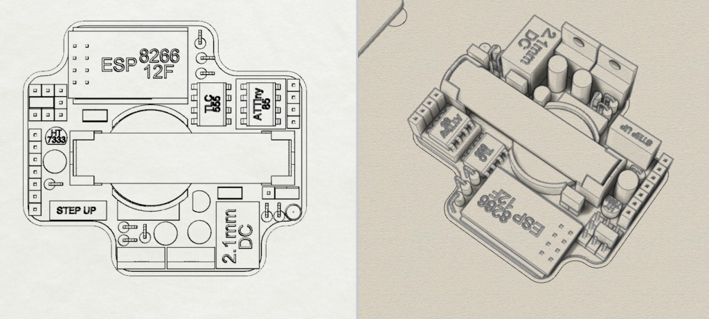
I think this might be as far as I can go prior to more parts arriving so I can take better measurements. There’s one more hardware feature I may be able to add being a wakeup pin, and I may also need to add 2 or so more headers but I can easily fit those now near the DC jack. Getting there!
Testing power options
I have been testing just how viable each power option is for this board, but it warrants a different article. Click here to see what’s going on.
Swappable Step up converters
I am thinking it might be possible to use a 5v step up converter to get an ESP32cam powered from either a battery cell or a AAA. This would allow for a webcam to run for a period of time off a single cell in theory, and it can be 5v as the board won’t be using any WiFi itself. The big issue is this means the step-up converter needs to be swappable as one of the purposes of this board is to be reconfigurable. The downside is this now requires a compact right angle plug.
Due to limited space I have come up with 3 options so far:
- Place standard female headers on the underside of the board. These will need to be SMD, right angle, and will also require part of the board to be cut away which I’m not keen on. But possibly the cheapest option.
- Place short female headers on the top of the board. Could be through hole or SMD, and right angle. I have been unable to find any of these.
- Use Swiss Machined Pin headers. These seem to come in SMD, and right angle, and are short by design. These are expensive.
The Swiss Machined Pin headers are by far the best option I have discovered so far. Now I just have to find them.
Update: Having trouble sourcing these things! So I have rearranged it all to support female smd connectors on the underside of the board. Not overly pleased with this but it will have to do for now until I can run more tests to see if swapping is even viable.

Once the capacitors and the 3.3v step ups arrive, I can then decide on what power options this has and in turn its applications.
More Eagle
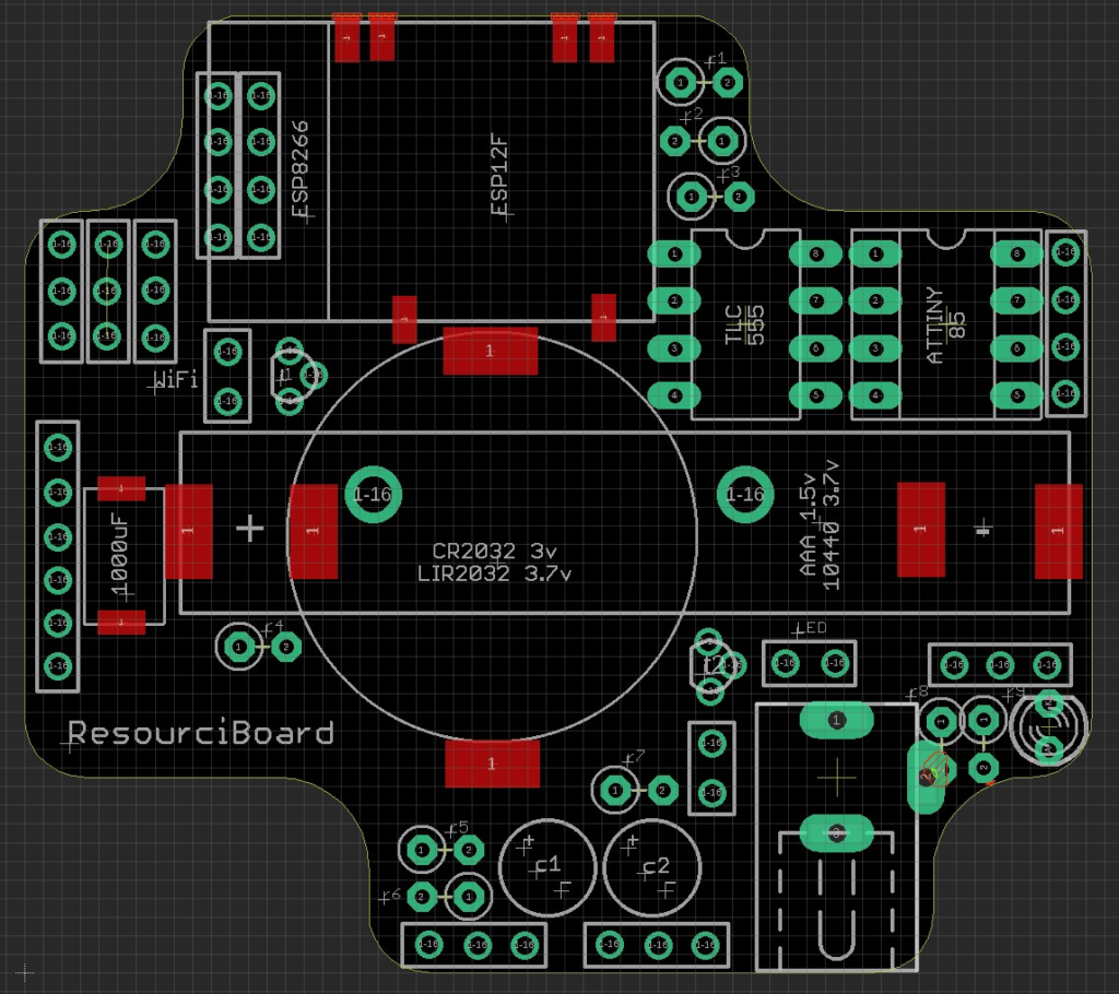
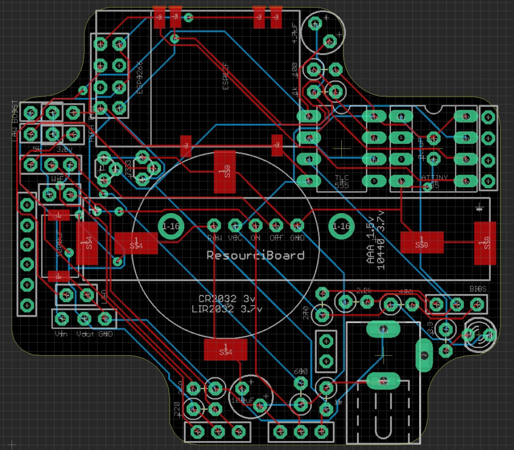
Decided to use my time to see if I could get a hang of Eagle again as it’s been a number of years. Once I figured out the controls it got fairly straight forward. So this is the rough board without the signals routed as I’m having trouble connecting traces to the centre of holes which I somehow worked out last time.
Update: I have been busy connecting and labelling everything so that I could run a test route and it looks good!
I am still testing different battery options and had some failures. For now, I have removed the coin cell from the board as it’s not a viable option – it’s not as common as AAA and holds very little current. The specific size I was trying (LIR2032) is unable to provide enough sustained current for the ESP32 component to start.
Battery Success
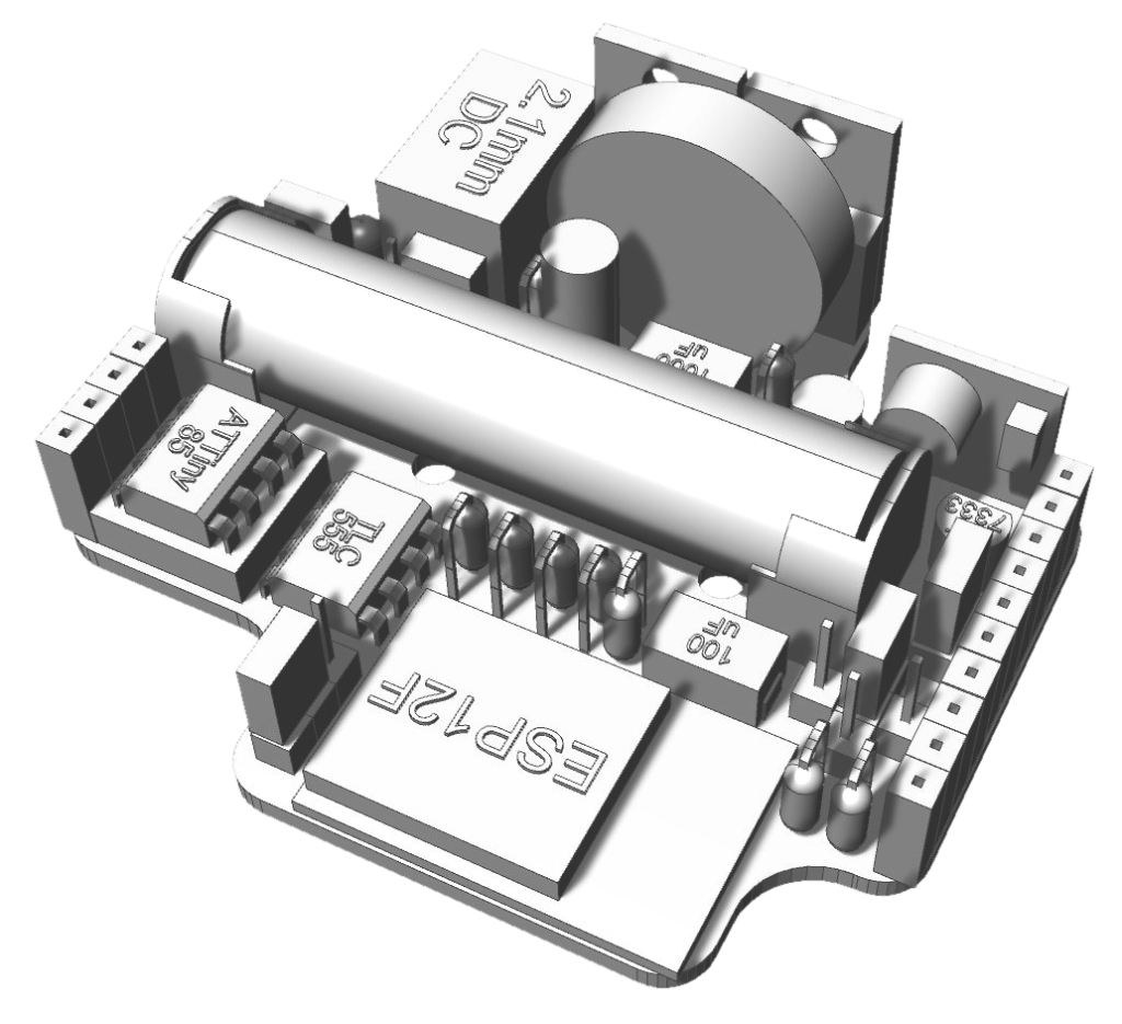
Ok after a very long time and a lot of trial and error, I have the general idea working off a single AAA. It has required a bit of rearranging on the board to accommodate a super capacitor but it still fits, and I can remove the female header issue from earlier. I’m not thrilled with the super capacitor placing – there’s only one other place it can go though. A bit more battery testing and I might be able to reduce the super capacitor down to the next size, which gives me a little more flexible placement. Once that’s worked out it will be possible to design the final arrangement for this.
I2C
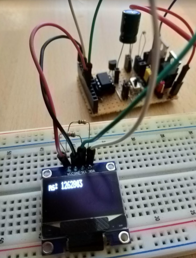
In an effort to squeeze as much out of this tiny chip as I can, I have figured out a way to add I2C to it so that I can now control tiny oled’s and such. This meant shifting pins around. Also I’m only having success running it at 5v so far, whereas peripherals are at 3.3. This isn’t great when using serial however a trick in a recent project involved running the 5v components with a diode, which brings the voltage down to 4.3v. This means it will register a 3.3v signal as a 1, allowing a 3.3v device to push data. Now with that sorted I went to try out the GPS theory with this off a battery and had success! We’re getting close to the final arrangement.
The I2C implementation used too much code to compile, so I ended up having to rearrange a lot of the code I was using, remove some loops, put some repeat things in to functions and now there’s just enough room to do things. Also I am getting a few odd things happening when connecting the ESP12 though, it must be a current sink on the pins or something to that effect.
I have decided to add a BIOS which is a nice time to split this in to parts. Jump to Part two here.
