This is a continuation of a long story. Go to the beginning, or go back to the previous page.
Protip: when you want a specific image to appear in linkedin, stick it as the first image and make sure it’s low resolution of about 1024×768 or so.
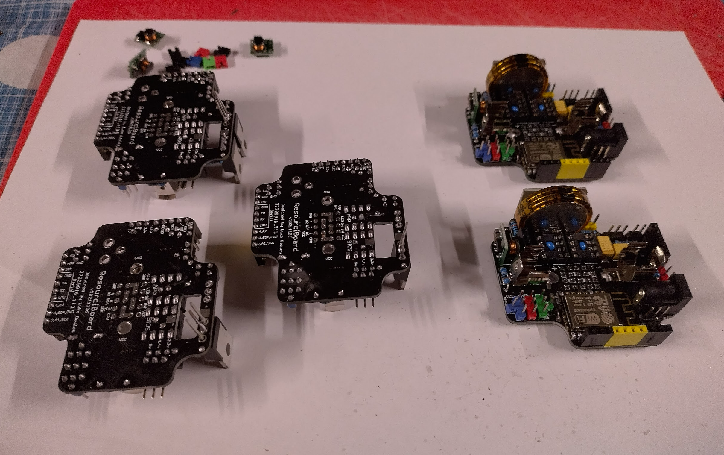
Assembly Line

With all the parts ordered and finally a nice enough PCB to spend them on it was time for a mass assembly. This would allow me to test the small QOL changes on the board along with giving me enough devices to test how they would work alongside eachother. I initially wanted to only make 2, incase the board wasn’t good. That quickly changed to four. I set up the soldering station and got to it.

I then thought I might have enough parts to do a fifth, and that would make for a great photo. Lets get another one in.

Day turned to night and I wanted to complete them so as to not use up a whole weekend, so I got up to the part that I dreaded.

The return of the soldering issue
I discovered an issue back with the neon style sign project specifically the 16 channel MOSFET switch where soldering the legs of these large 3 pin components is a bit iffy. The issue being that the solder will cool too quickly and end up doing unpredictable things like joining tracks. And due to the solder cooling quickly, its very difficult to fix. Unfortunately 3 of these boards had the issue.
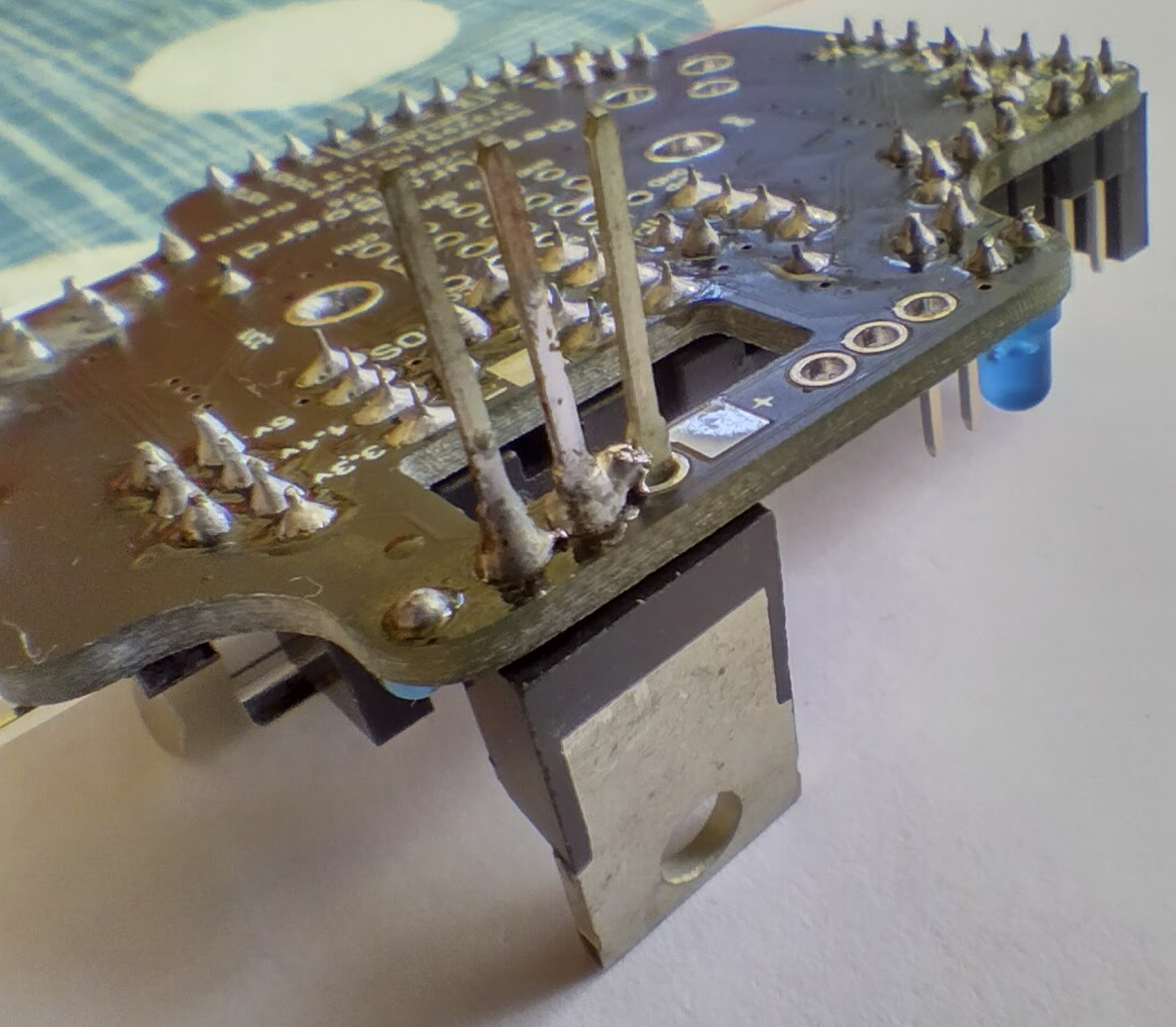

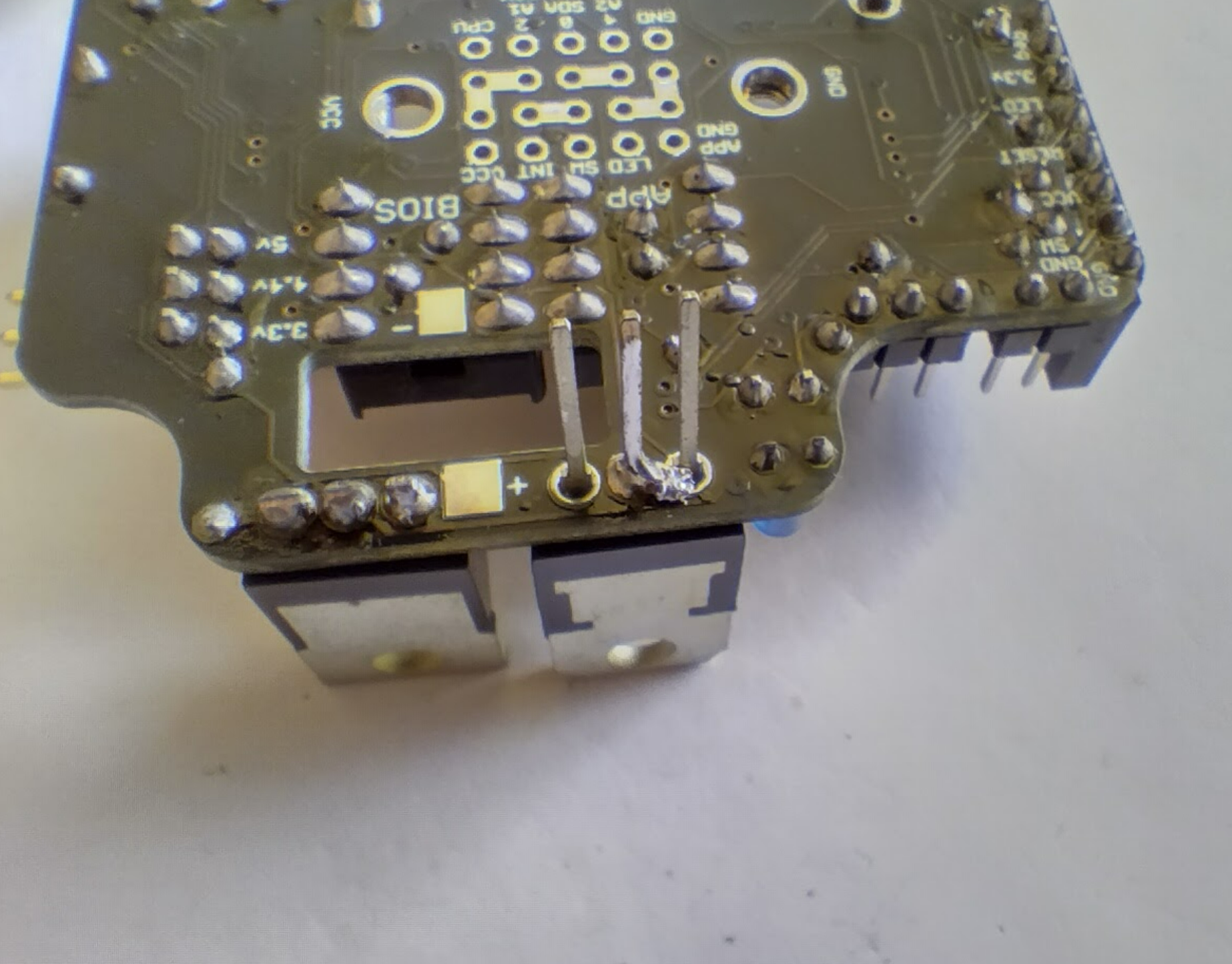
I decided to call it a night and think about it. I tried solder wick but it doesn’t heat up enough of course, and a solder sucker is on its way. I read a trick earler about how to clear solder from holes which was to use a safety pin as the solder doesn’t stick to them. So my plan was to heat up the solder as much as I could and flick it away with the safety pin. It worked! With that sorted, I could complete all the boards after a marathon run spanning two days.
I have since discovered that the trick might be to do the following:
- Let the iron get hot for a few seconds
- Put a blob of solder on the iron
- Stick the tip as vertical as possible pushed up against the leg, and pressed against the hole
- Watch for solder to appear or go shiny on the pad/hole, and at that time slowly add some either to the leg or to the iron whichever works.
This seems to work but I’ll try it next time. Also the middle leg seems to be the one that sucks the most heat out.
The order of assembly
I have been refining this process over the 3 versions, but due to the solder issue above I think I might need to do that step first to see if a board is going to be faulty first. However here’s the steps I took:


A complete set!

With the boards all made, it was time to give them something to test. So I put together the sub boards that I ordered at the same time.
A these will need a bit of testing, the only one that I am certain works is the OLED. But the changes for the Camera and GPS to get them to fit in the enclosure better seem to have worked.
The Pager board I need to fiddle with resistors and capacitors and voltages to see if it’s any good. I’ve had 4 lights flicking away on my desk for over a month now testing the theory and it seems ok.
So that’s it, over to testing that the components on these are all good, then it’s on to firmware to see what I can get going reliably.
Firmware Updates
I have been feverishly testing and managed to get the ESP32Cam and GPS boards going fairly stable, but still having issues with the Pager board and Oled with odd resets.

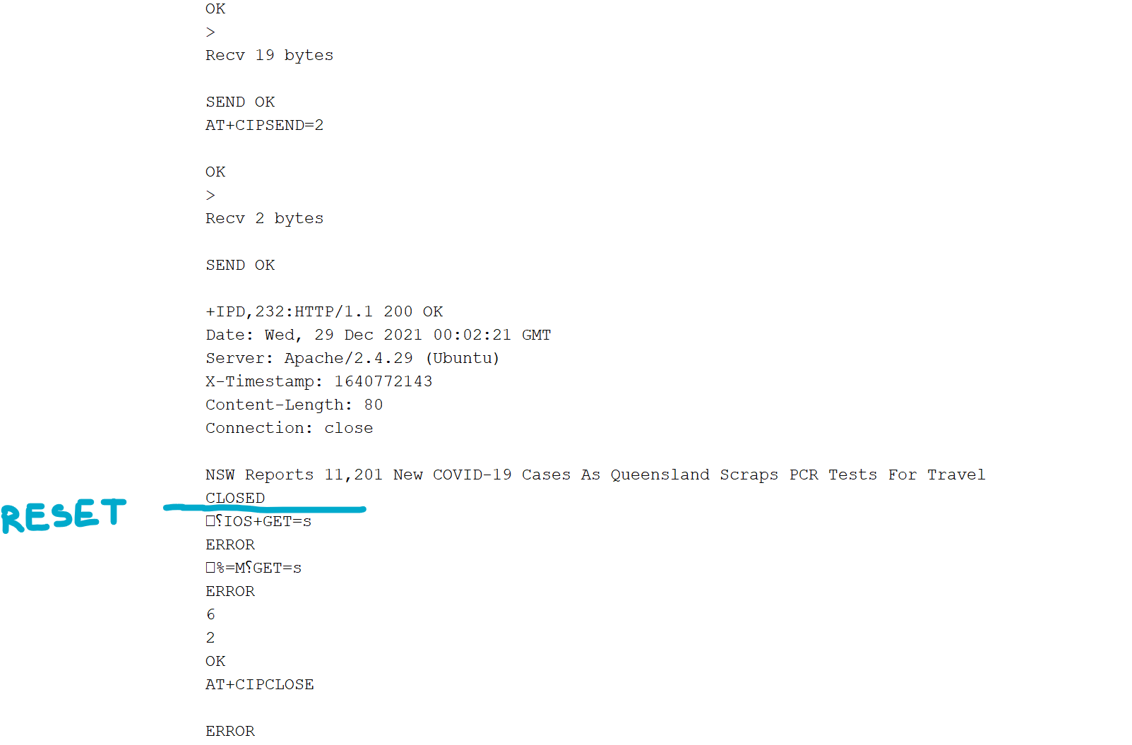
The issue seems to be when trying to capture the results of a page load and looping through it which both these boards require. It resets the APP chip instantly yet the bios continues. This is also an issue regarding the replacement of the giant alphanumeric display board which is what I’m attempting to do currently (ha!).
I’m thinking this might be power related as there’s a lot going on at this point and I may have narrowed it down. In order to get the BIOS to work in 8k of space I removed power saving months ago, so it stays at full power. It also receives all the serial data and interprets it. So I have two ATTiny85’s both filtering through serial data at the same time. This along with the ESP12F all sucking down power might be too much of a blip causing a reset.
I have added back in the sleep command so now the bios sleeps for 125ms at a time, at the cost of a bios data validation check as the bios seems pretty stable. This will wake up whenever serial is received of course which doesn’t help with the issue. I have also added a BIOS+SHH command to tell it to stop listening to serial for 10 seconds. This should allow full power to go to the APP chip.
It’s a difficult one to debug but I hope it works.
Update: BIOS+SHH didn’t help, neither did the proper sleeping of the bios chip. I have also tried getting the chip to sleep as soon as it receives content but that failed. I don’t think it’s a power drain issue otherwise the BIOS would reset at the same time, as would the ESP12F. Is it a compiler issue?
Update 2: Tried a lot of code changes, it seems to be if I sift through the data that is directly returned from the website. If i look for data that the ESP12F returns as part of its AT set then it’s good. It’s once it gets in to the returned web headers or content. Something is different there, is too much is sent at once causing an overflow?

Update 3: IT WAS THE WATCHDOG!!!! What a relief, but also what a painful discovery that it had been the watchdog causing the odd resets for nearly a year. It seems to be if there’s a delay or a bunch of interrupts (caused by a lot of software serial data) it would make the ATTiny85 think it’s stalled, and trigger a reset. So if anyone is in a similar issue – it’s not a power issue, it’s not the compiler, it’s not a brownout detector, it’s the watchdog. Success finally, but on to the next issue!
The watchdog issue has solved most of the issues that were appearing, there’s still the odd occurrance but seems like it’s coming good. It’s over to seeing how many different applications I can get to happen with this now.
Practical Uses
Since the board seems to be 99% good just requiring a few small adjustments, I am on to the firmware and sub-boards and I have decided to go all in. The OLED and ESP32-Cam boards seem ok and I have spare modules for those, so I have made all the boards ready.

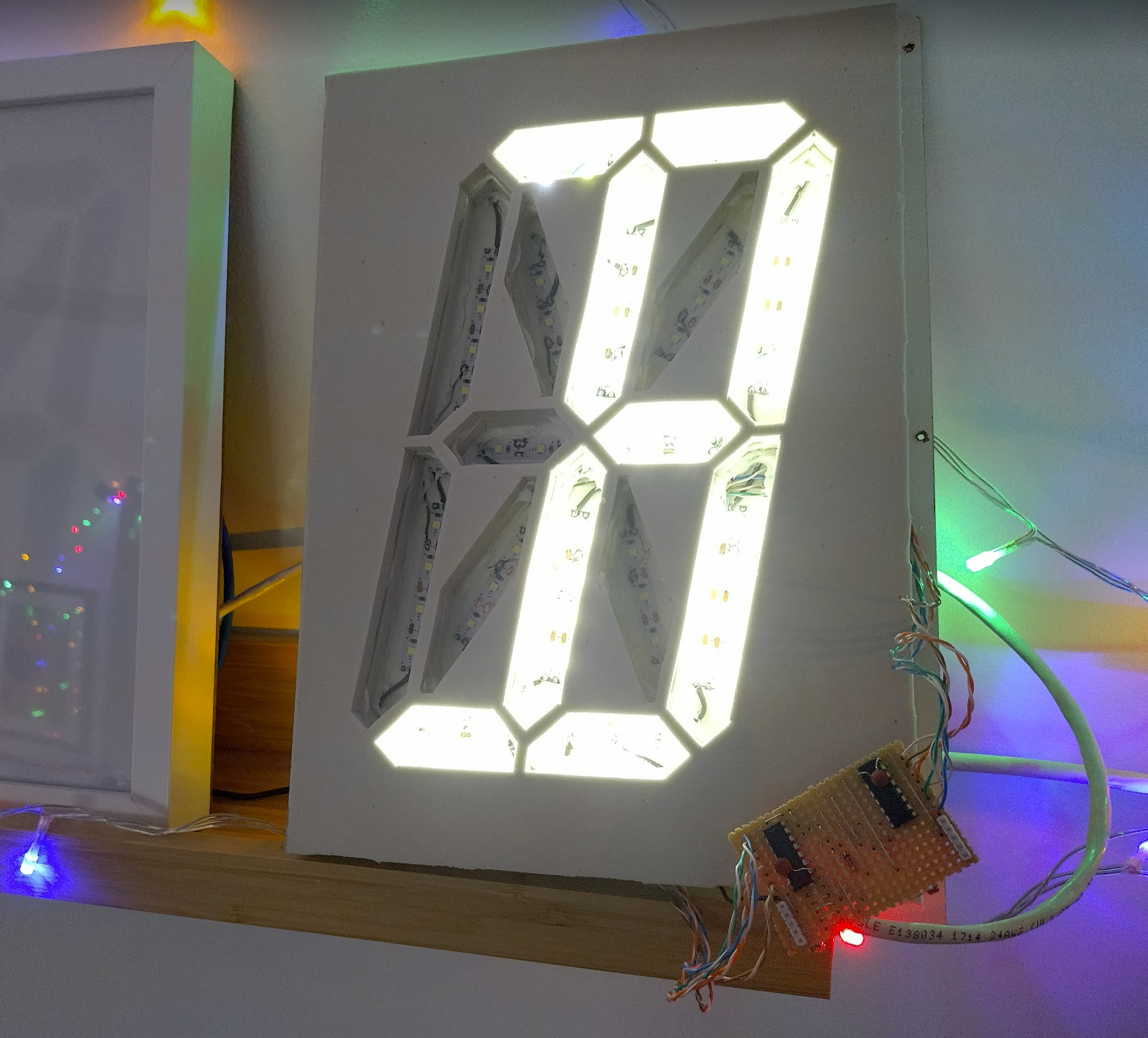
And one of the main aims of this board was to be flexible enough to replace the giant alphanumeric display controller – which has been powered with one of the original non-bios ATTiny85 boards for about 8 months solidly now.

A fair bit of diagnostics with faulty boards and extreme voltages destroying one of the digits, it’s now complete and working with just 5 digits!
Just need to keep an eye on it to see if it succeeds, and then on to getting the pager working correctly.
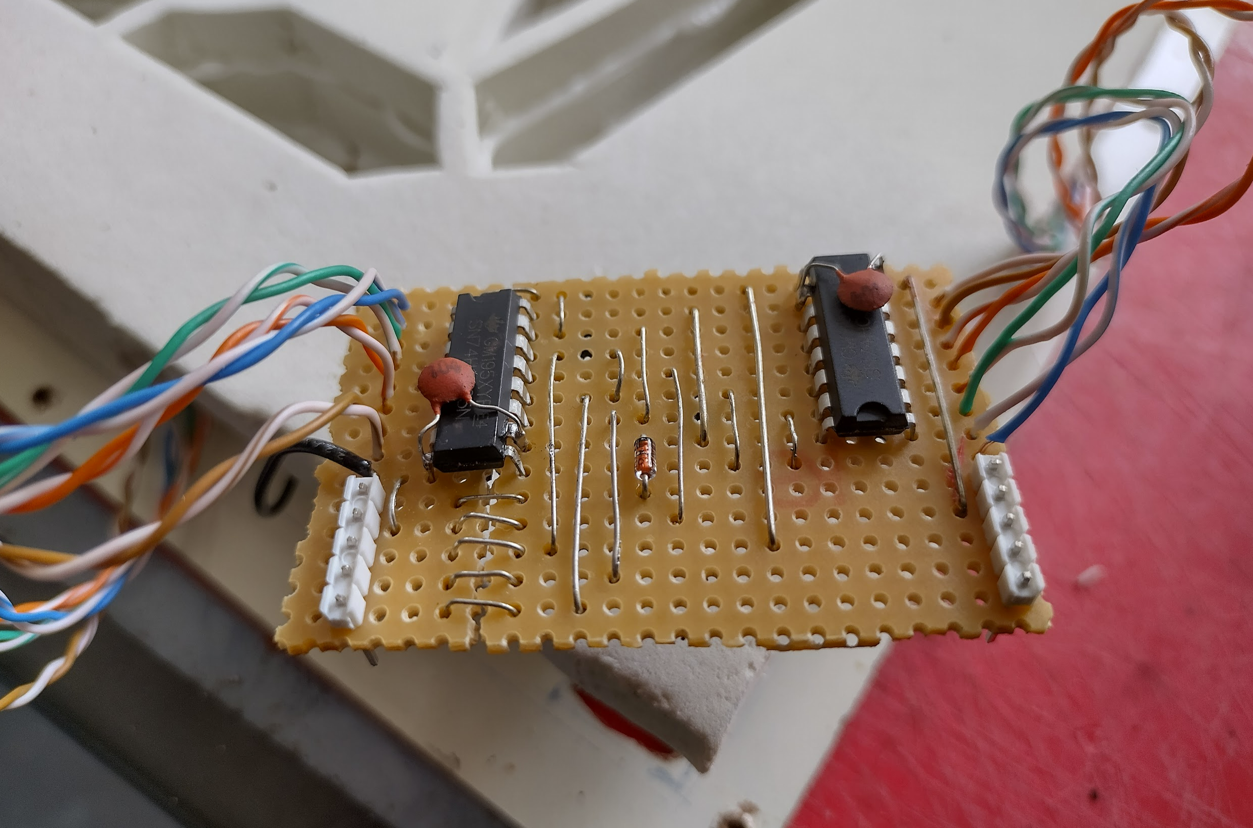
Update: I repaired the sixth digit for the giant alphanumeric display – the issue was I powered the shift registers with 12v unknowingly for about an hour. So I tested all the led segments to make sure they were still ok as they’re all 5v, and luckily they were. I then created a new board out of the veroboard I had remaining, with two new shift registers and hoped for the best. It seemed to test ok so this was all put back together and linked up and it’s all good.
Paging Dr. Luke
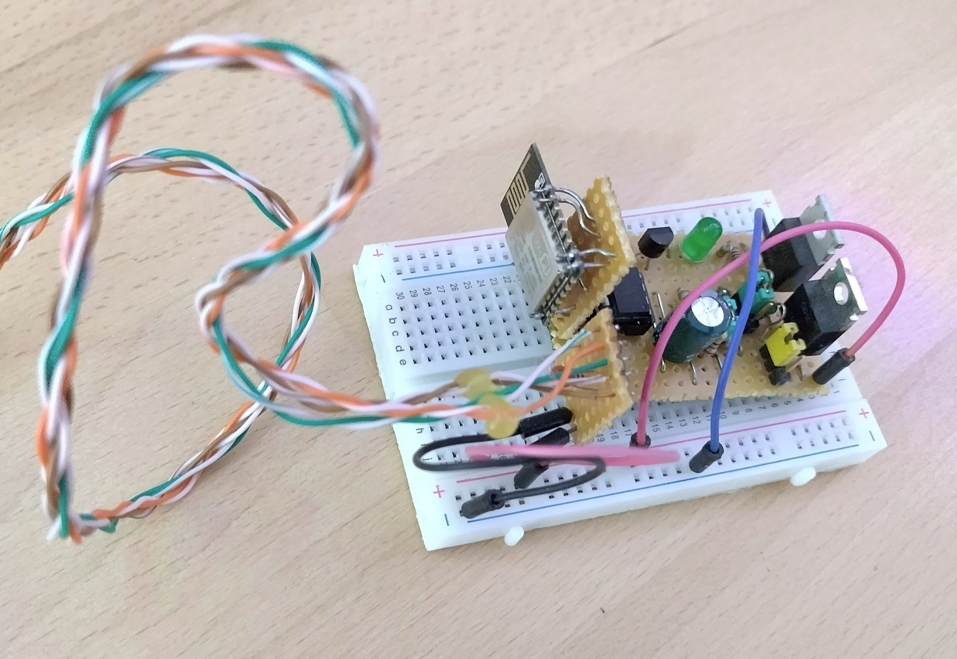
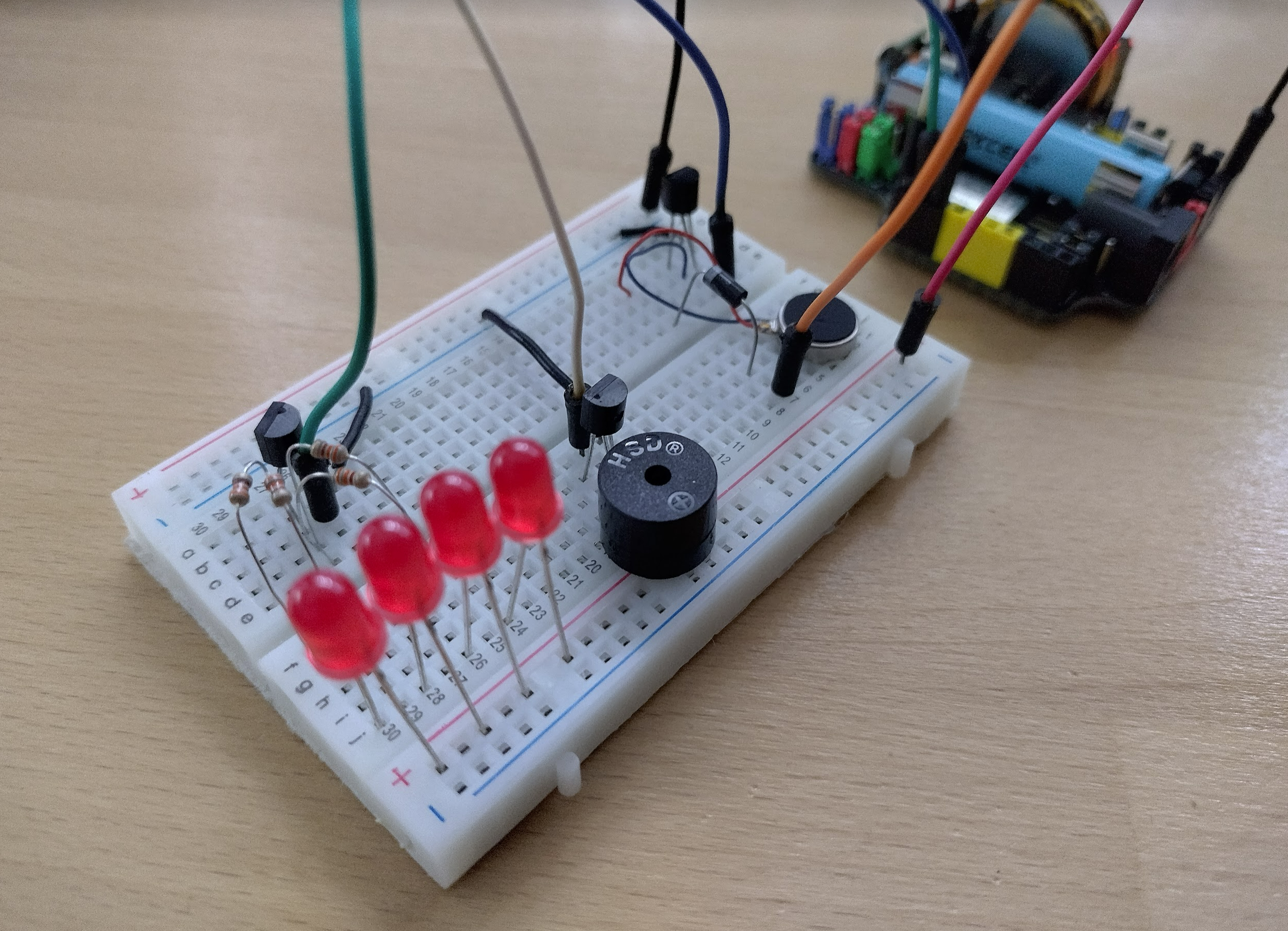
The last remaining puzzle is trying to get this pager system to work, where the device will read a list of ids from the internet and if it matches its own id in that list it will trigger an alert. I put together some breadboard samples, worked a lot on the firmware as I kept finding odd issues but in the end I had success! Two meal pagers!
This finally proves all aspects of this board – sending data, receiving data, acting upon that data, SPI interface, shift interface, battery power, etc. I have a working GPS board along with ESP32-Cam, and OLED. I need to do a few modifications and design an updated pager board along with a shift register board. Then I will have a nice array of products.
Update: I have refined the pager board to contain all the leds, a beeper, and a motor in a deconstructed state and it works nicely. This just needs to be put on a PCB next.
ESP32Cam changes
This is just because I could only find one note on the internet about this. The original ESP32Cam and sensor would take photos in the correct orientation when lying on the longer side (with the led on it). The new ESP32Cam and sensor takes photos correctly when sitting on the short wifi side.
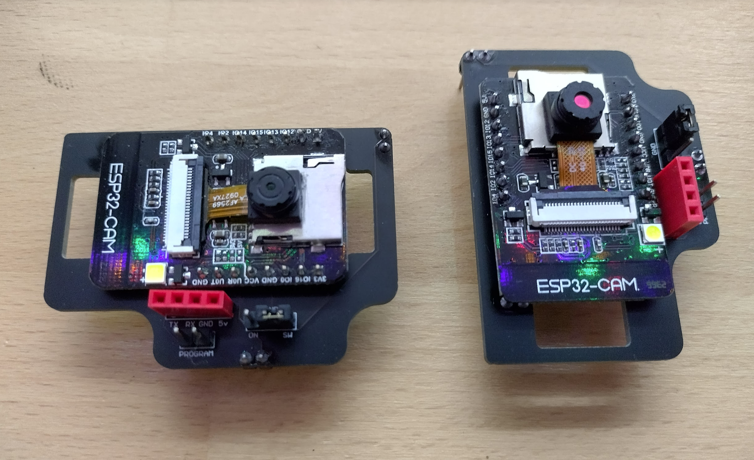
There doesn’t seem to be a way to rotate from within the camera itself that I have found yet – so the easy answer is to rotate once it’s uploaded or orient it according to the sensor.
I haven’t discovered any other obvious image quality differences between the sensors.
Hope this helps someone.
Almost there
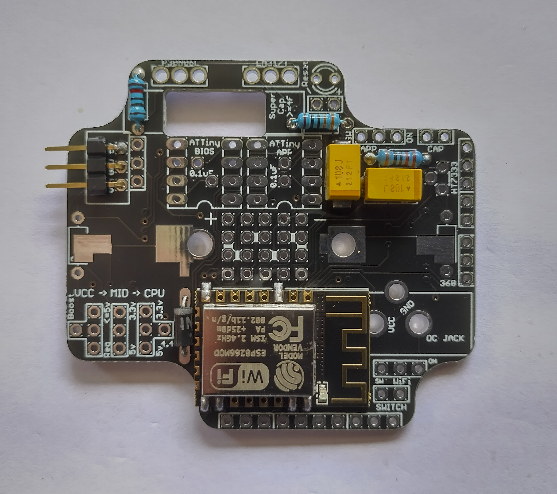
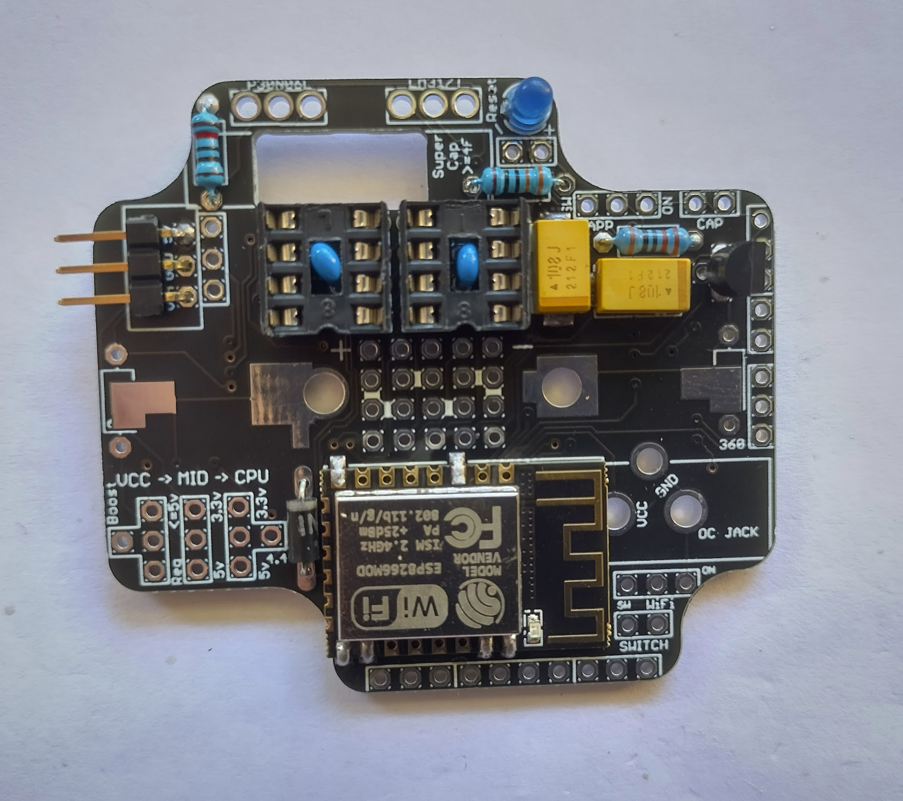
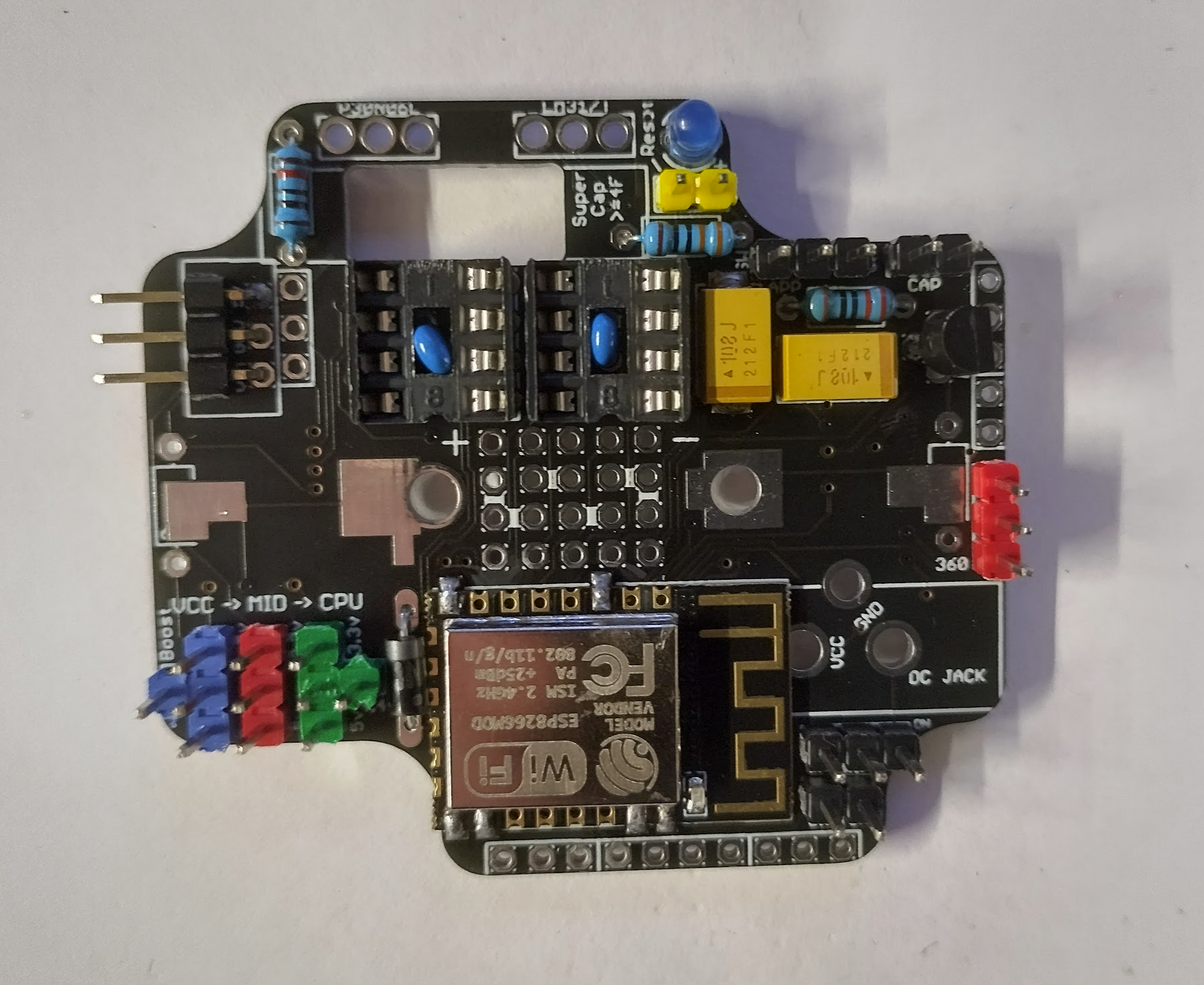
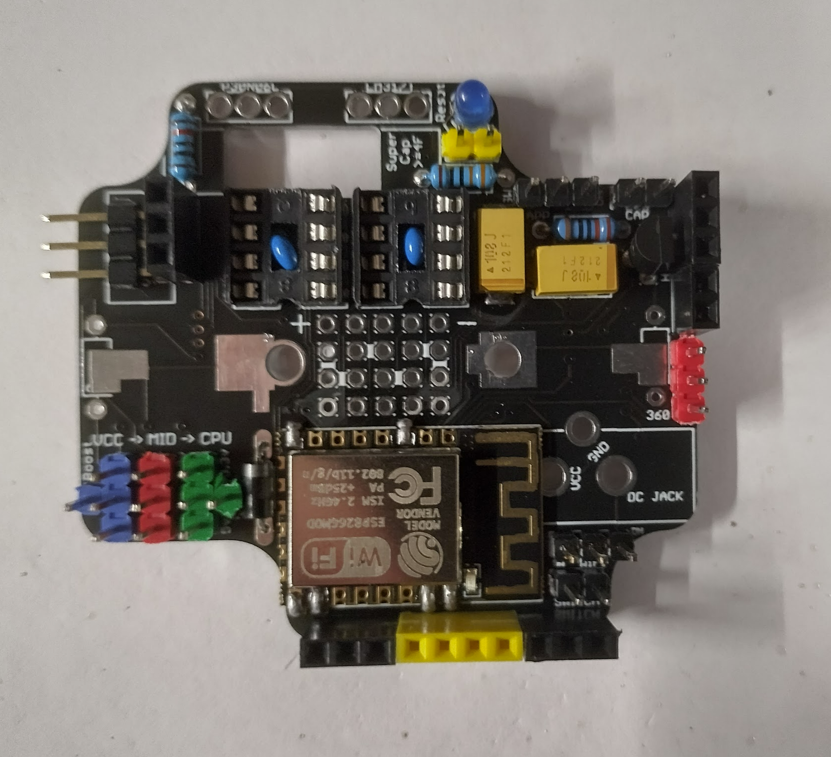
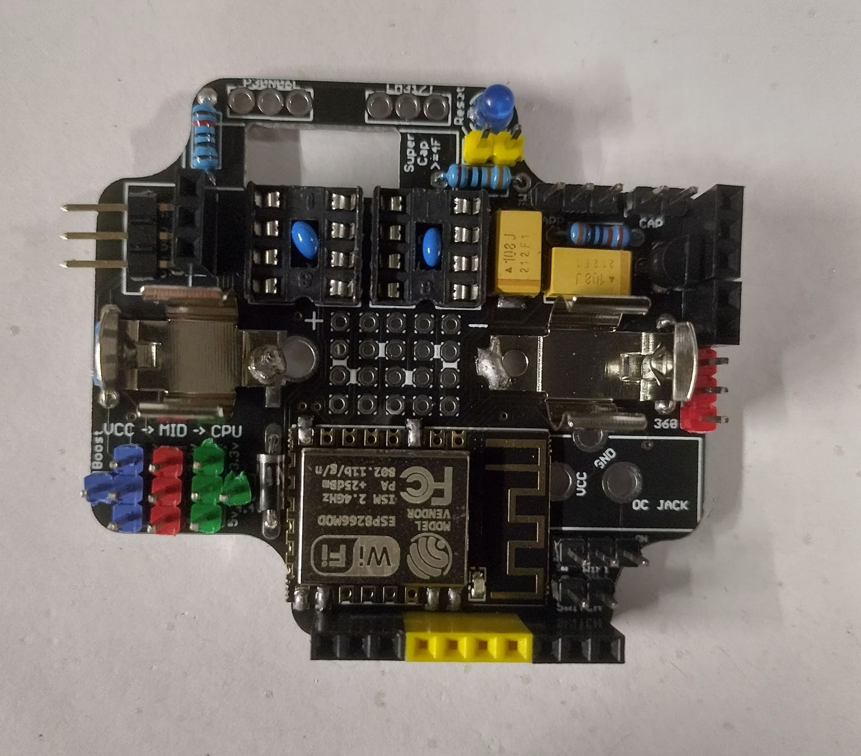
I have refined the ResourciBoard a little by fixing up mainly labelling issues along with moving some pins very slightly to make soldering easier again. I decided it would be worth getting a few other boards done so I now have these boards:
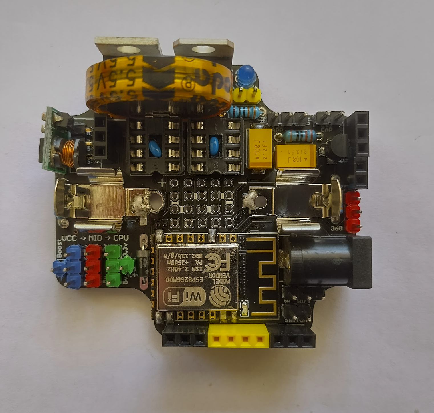
- Main ResourciBoard – This is what everything plugs in to providing the power, settings, cpu, and wifi/bluetooth
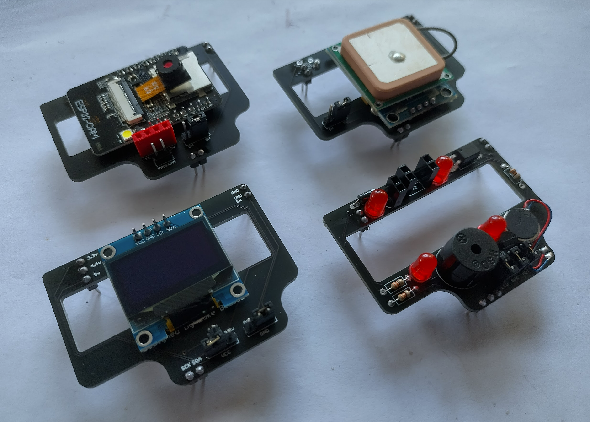
- ESP32-Cam – Houses a camera that pulls its settings from the main board.
- GPS – Pushes the GPS data over two serial lines for the CPU to parse and push to the internet.
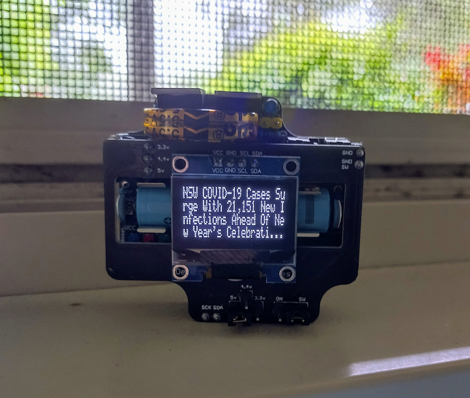
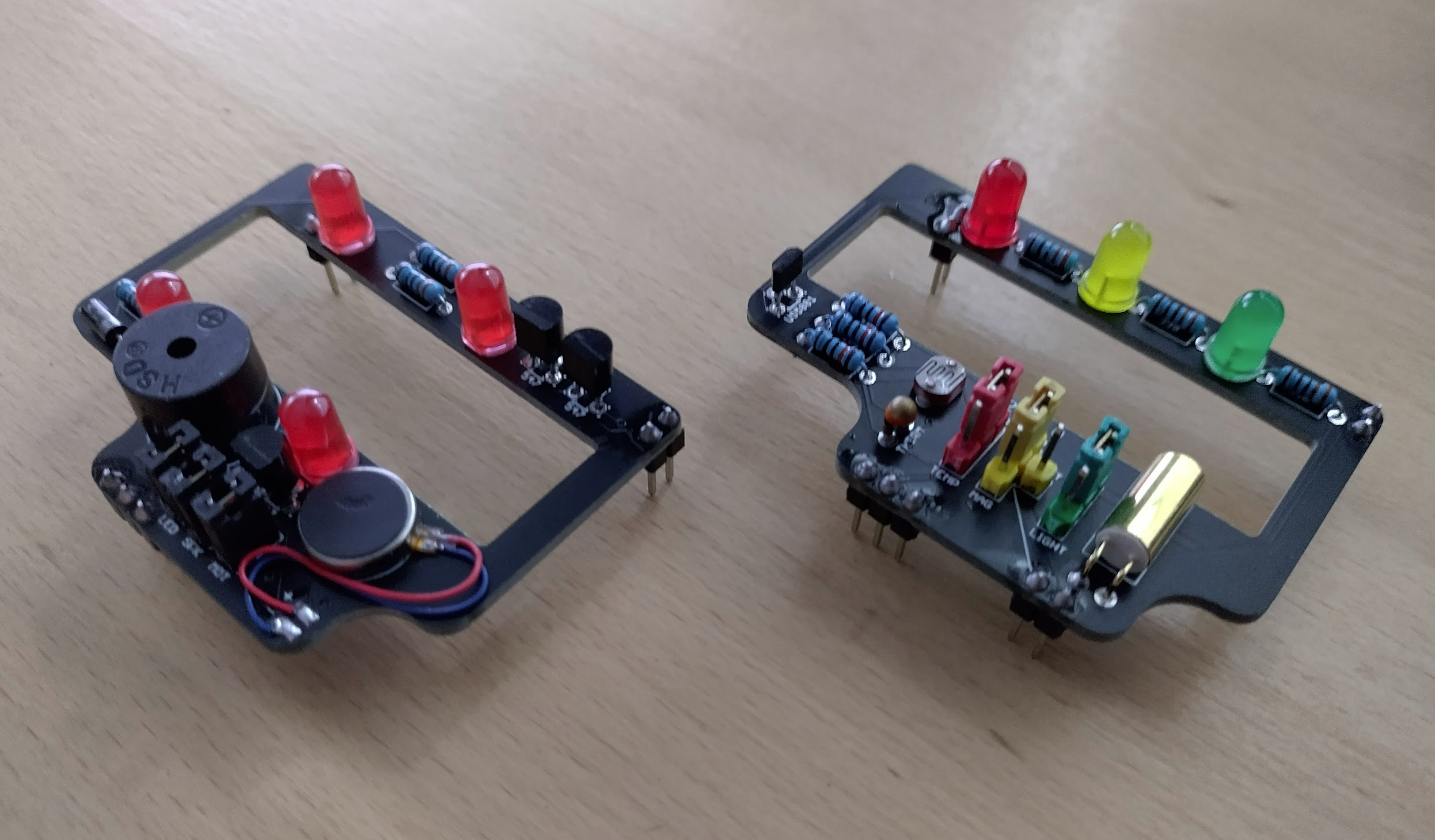
- OLED – Displays the content that the CPU chip pushes to it via I2C
- Pager – Beeps, Vibrates, and Flashes 4 leds on the CPU’s command
- Shift – A stackable board that should be able to either power 8+ outputs, or sink 8+ inputs. This should be able to duplicate the functionality in the giant alphanumeric display and the neon style led sign.
- IO – Can read temperature, light, and magnet / tilt, or switch on 3 different leds depending on the configuration. The tilt/magnet can also tell the board to turn on.
This is a fairly comprehensive list to show what this system is capable of. The boards are all on their way now, and I have been busy purchasing bulk parts to make about 10 of the main boards and anywhere between 3 to 20 of the others. This required a spreadsheet to keep track of how much of each component, where to find it, the cost, and to automatically work out how many of each board I can make based on stock and incoming.

With that all ordered I also decided to try the sealed enclosure with usb DC jack power by carefully measuring and placing a hole. This turned out exactly as planned way back in the beginning.

So with 3 boards being tested over the last couple of weeks with different powered methods I think it’s pretty good. It’s now over to drilling a few more holes to get some more of these enclosed, and waiting for the new boards and all the parts to arrive.
The second most expensive clock (in man-hours)
Parts have been trickling in but it’ll be another week or two before I can start assembling the new ones. I have been busy trying to make the OLED board a little more useful and educational than just an extremely small news ticker and I came up with an auto setting clock.
The OLED board is proving a bit fiddly as it seems to disrupt the bios connections. This was the successful one but in an attempt to have two clocks running I am struggling to replicate it. Still, the working one looks great. And it should be fairly battery friendly. The OLED still uses a bit of power so it would probably last a few hours.
I have also been thinking how can I get the 3 available pins outside of the enclosure so this turns in to a fairly modular self contained device. Early on I wanted to use a headphone jack but didn’t have the space. I think I have worked out a way which consists of moving the two tantalum capacitors to the bottom (or nested within cutouts), and the ht7333 and one resistor to the bottom also. Along with a bit of shuffling of headers this will open enough space for a headphone jack at the top right. This will unfortunately require all new sub boards, so I’ll wait until v2.0 for this hefty redesign.
New boards have arrived!
The newest round of boards are now here. Here’s the complete ensemble of the latest versions of all the boards.

I have been busy getting decent photos of how these can all be used so that I can do a nice writeup of it. I already have the GPS, ESP32Cam, and OLED boards constructed and tested. The ESP32Cam has been running a true outdoor test with a heap of nasty rain forecast for this week and hot temperatures it should take a bit of a beating.
I don’t have the parts yet for the Shift board, but I have enough to make the Pager and IO boards so I have been busy soldering.
These two boards are the last remaining ones to provide purpose to this whole idea, expanding the use cases to 6 – with these boards being able to add multiple uses each.
I am waiting on a lot more components to arrive but hopefully in a couple of weeks I’ll be able to have 10 – 15 ResourciBoards all doing different tasks. At that point is when it swaps over to getting the platform a bit nicer for these.
It’s all coming together
All the parts have arrived, and I have been busy making 3 new boards and testing the other subboards along with a few power theories. Everything is going good so far.
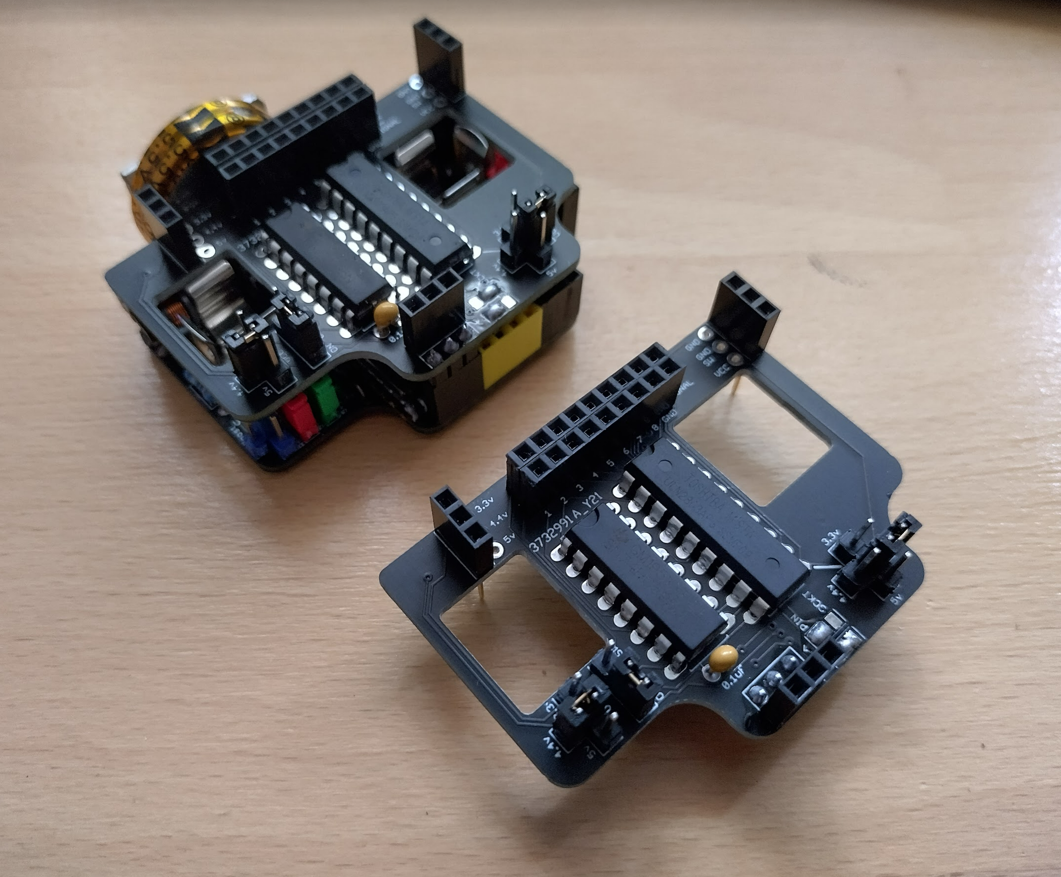
I constructed two shift boards, and tested both the 74hc595’s and the uln2803’s, along with the stacking theory and it all worked first go!
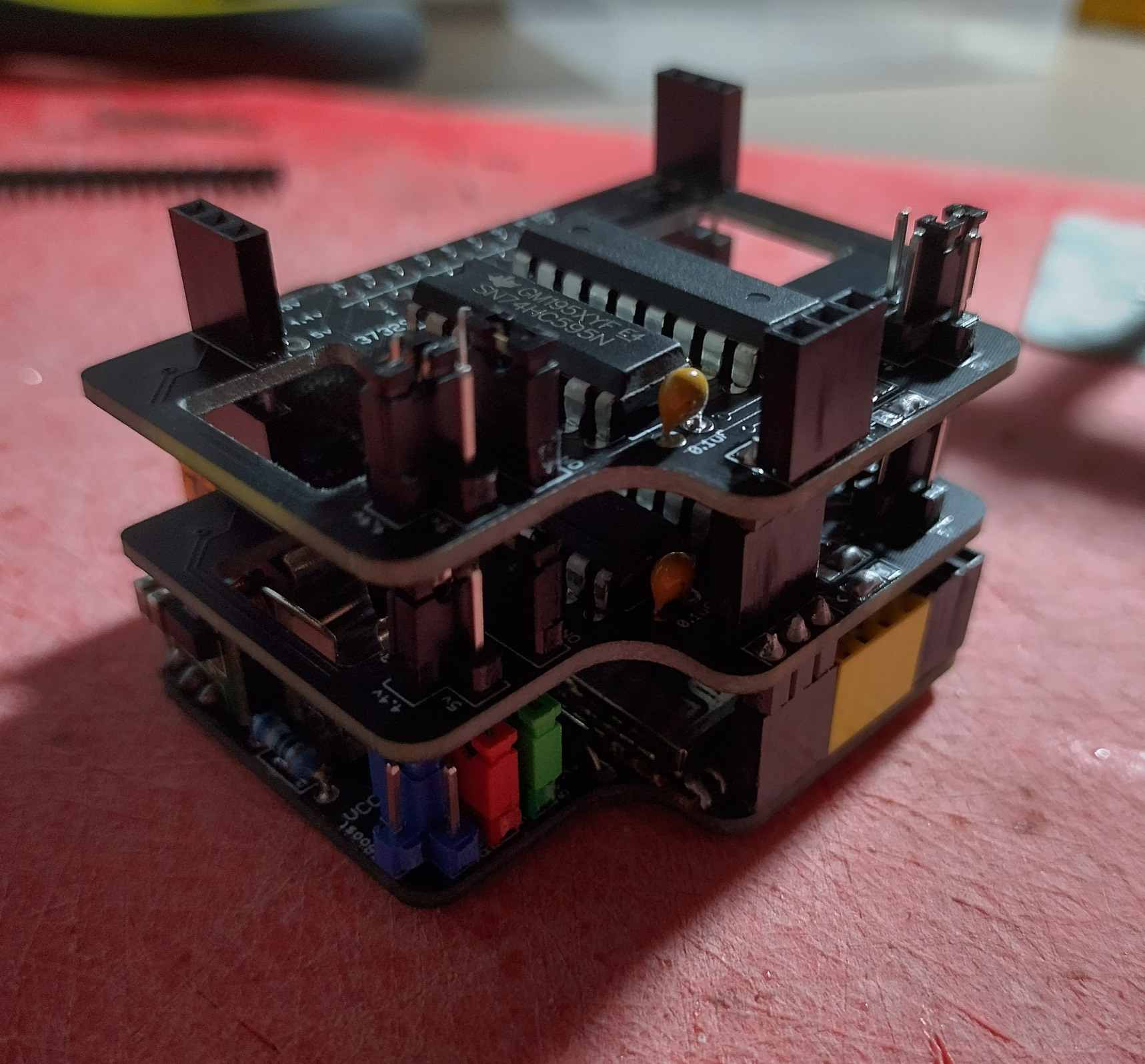
I have had 16 leds flashing in an old test pattern with a stack for about two weeks with no hiccups.
This shift board now allows for arrangements like the Giant Alphanumeric Display to have 12v segments rather than 5v, and the Neon Style LED sign to have far simpler wiring as no MOSFETs should be required in theory.
Then it was on to proving the pager board. These were a bit tricker to get working due to a difference in esp12f firmware, which reduces the delay between sending and returning data from a webserver. Once that was solved the pager board was proven perfectly with me being able to trigger two boards independently.
An important part of the battery theory was to have it so the battery could be charged while the device was running. This would allow the enclosure to be sealed for as long as the battery is good, making it truly weather proof and portable, so these devices could be handed out and returned once they trigger. I got my hands on a tiny LI-ION charging board and set it to test.

It worked as planned. With it all triggering each minute, the battery still charged while plugged in, and drained while unplugged. Proving this device could sit on a charging station and be handed out to people. It also proves the theory that this could be powered by solar during the day, and battery at night.
There’s only one more part of this to be tested, which is the interrupt trigger and sensors then it’s all good! But for now I have 5 more boards to make giving a total of 12 running devices.