Click here to go to the start of this journey, or here to go to the previous page
Since the last page there hasn’t been so much prototyping as it has all come together nicely. Most elements are tested with only four major issues that come to mind:
- The tilt sensor on the IO board doesn’t trigger the wakeup interrupt. The Hall effect sensor does, so I feel it might be that the pin is floating and needs a pull up/down resistor on it.
- The internal serial bus shared between the APP, BIOS, and ESP doesn’t work correctly unless the ESP is switched on. This again feels like the pins are floating. Not an issue when the APP chip powers up along with the ESP, but in instances where the APP chip is required to keep pins high or low it needs to stay awake. A workaround has been put in place where the APP chip pings the BIOS. If it gets a successful reply then it knows everything is awake. The issue with this is the APP chip can’t tell the BIOS to wake up.
- There’s no way to get the 3 APP pins outside of the enclosure yet. It is possible to fit a headphone jack where the tantalum capacitors sit, and move them + a few resistors to the bottom of the board but this requires a significant rerouting of the ResourciBoard and the sub boards – so that is for ResourciBoard 2.
- The screw mounts to get the battery terminals to the bottom of the enclosure are too tight and some traces are too close to the mounting holes. The screws may have to be replaced with tight fitting pins instead if that solution is to be used. If waterproofing isn’t required but charging still is, then the DC jack will suffice.
The above 4 issues aren’t show stoppers so I am moving ahead as the rest of the features work very well.
Testing extravaganza
It’s on to testing! I have 11 devices that have been running for some time, proving all voltages are ok and the capacitors hold well.
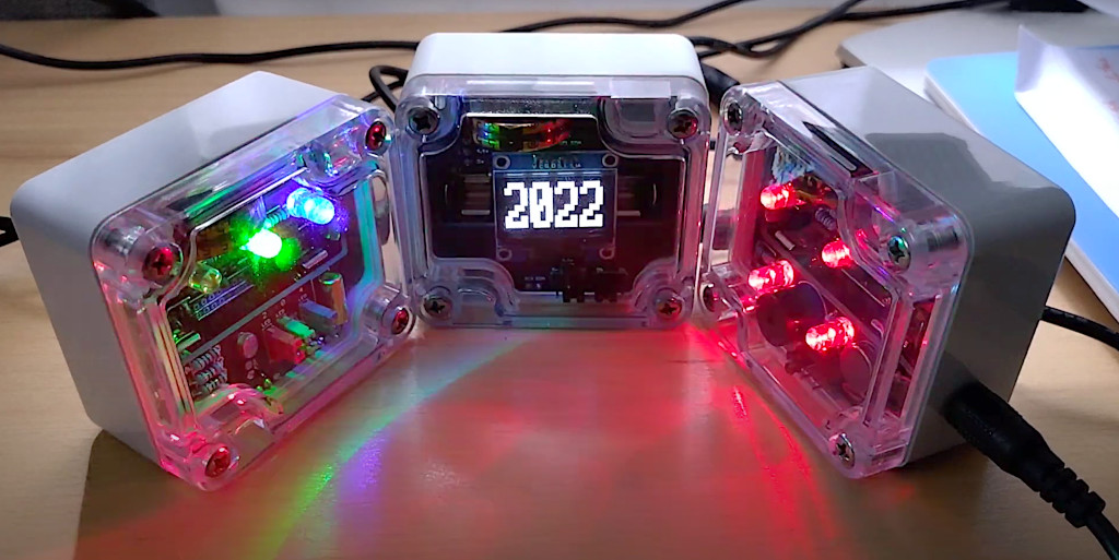
The devices that are being tested are:
- 2 x OLED clocks
- 1 x IO led status board
- 1 x IO sensor board for temperature, light, and magnetic
- 1 x Pager board
- 1 x Bare board driving the giant alphanumeric display
- 4 x ESP32-cam’s. One of those with a wide angle lens, another with the onboard flash, and a third positioned outside in the weather.
- 1 x GPS board
These are all feeding in to a web application controlling these devices.
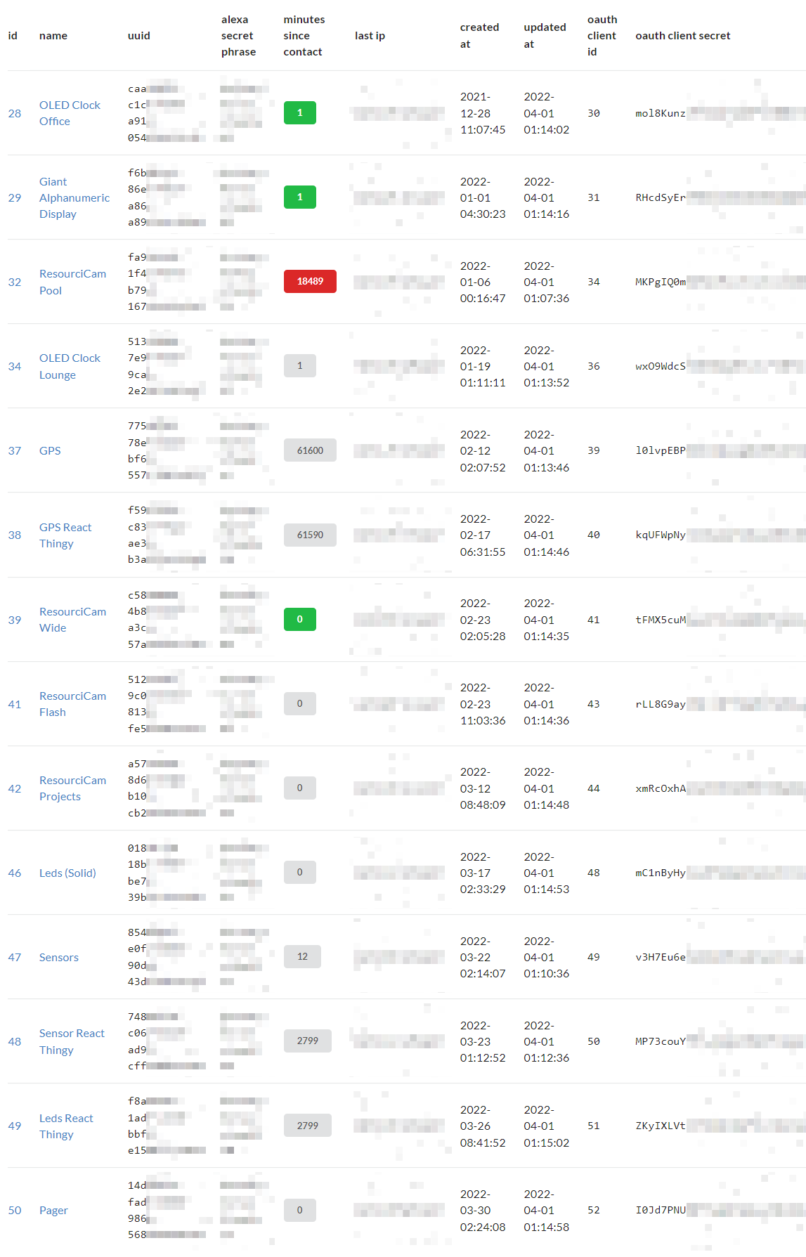
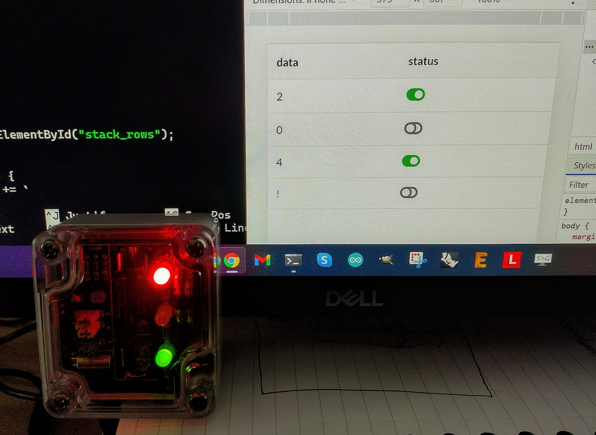
The more interesting ones are the pagers and IO sensors. So I have made a quick responsive JavaScript application to trigger the individual leds, trigger pager devices to go off, and to monitor the sensors on the IO board.
This becomes more powerful when the cloud server can trigger one boards leds or outputs, based on what another board reports. This then all ties in to the Alexa integration, and having the giant alphanumeric display showing the status of other devices for example amongst the news.

So it’s more towards the APP and SaaS development at this point to get these devices more integrated. Then it can be a commercial product that will find its niche!
Moving to real-time
I have been looking in to websockets and if I could extend the ResourciBoard to connect to and use a socket without much trouble. So I added a socket function to create all the necessary headers and a few filters, made a quick websocket server, and gave it a go.
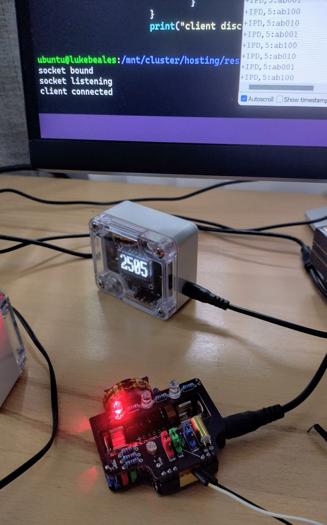
With the board reacting to the websocket data after a few fiddly filters due to serial data, it now runs reliably and reconnects automatically, making it a true IoT real-time device. I added a small mobile test app to turn each led on and off instantly to prove it.
This is still leds, but the goal is to turn this in to a driveable device. This will require a small servo (previously proven) on the PWM pin, and the remaining two pins controlling a L298N based board. This will give me steering, and forward/reverse. I’ll base this around 30 year old lego technic components and motors to make it an easy starting point – which I have discovered is 9v.
The ideal situation is to have a ~9v battery pack directly driving the motor, reduce it down to 5v on the ResourciBoard which will then power the servo, and have an ESP32Cam subboard connected and running in streaming mode. This should make a web driveable robot.
Then it will need an app with maybe AJAX or socket calls giving the user forward/reverse, steering, and a view from the device.
Fairly ambitious, and it’s a much more manual and time consuming way of making what students achieve in high school, but have to keep learning!
With the v2 redesign of ResourciBoard exposing the 3 control pins via a headphone jack, it will make this a much cleaner pluggable design, but lets see if we can move something first.