This is a continuation of a project. Find the start here, or return to the previous page here.
When assembling the first working prototype I discovered a few issues, so a new version is on its way. I also created a few quick subboards to give this a little more purpose. So I can continue on with testing code until the new parts arrive in about 3 – 4 weeks.
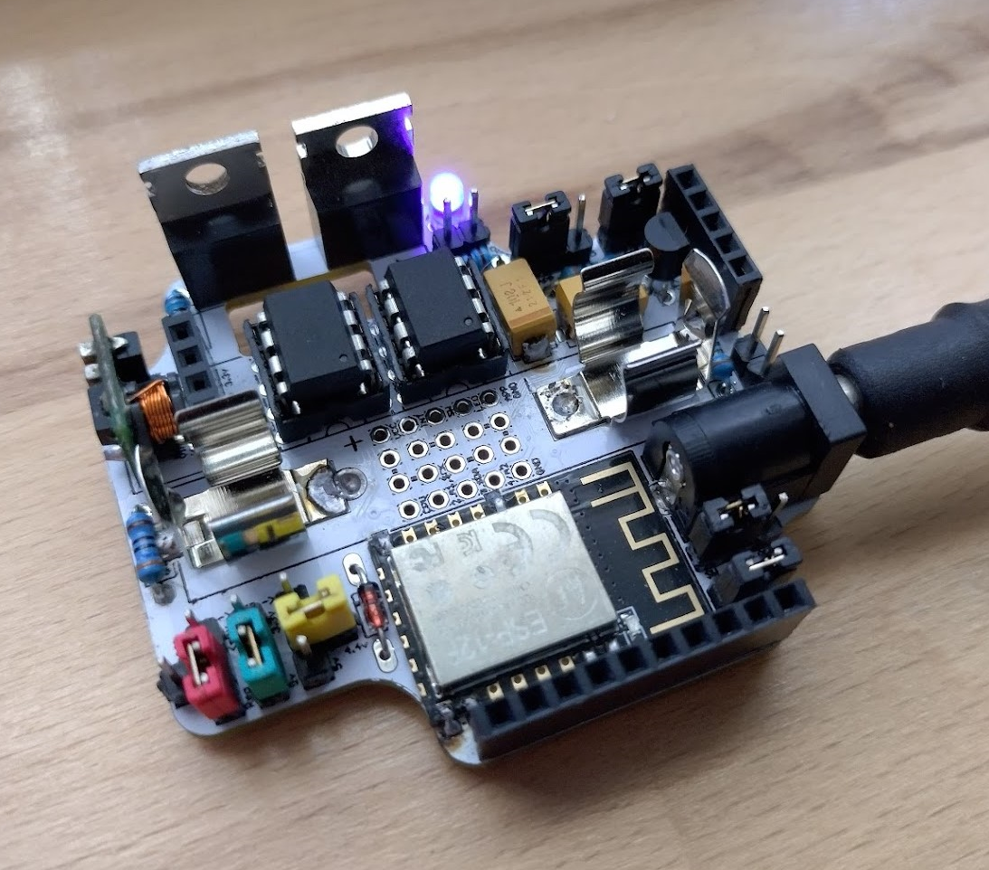
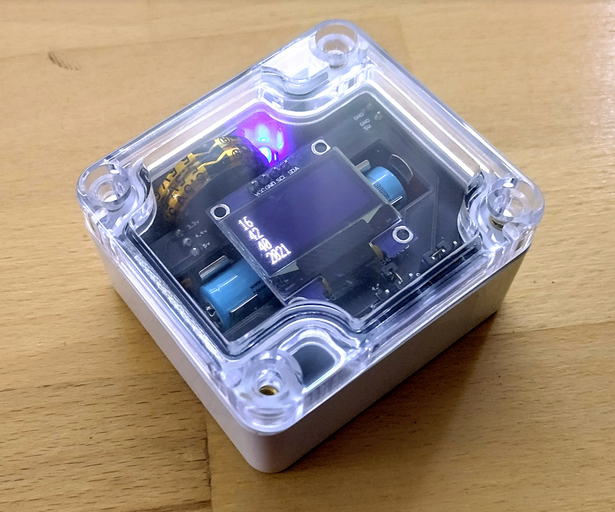
A 100% complete board
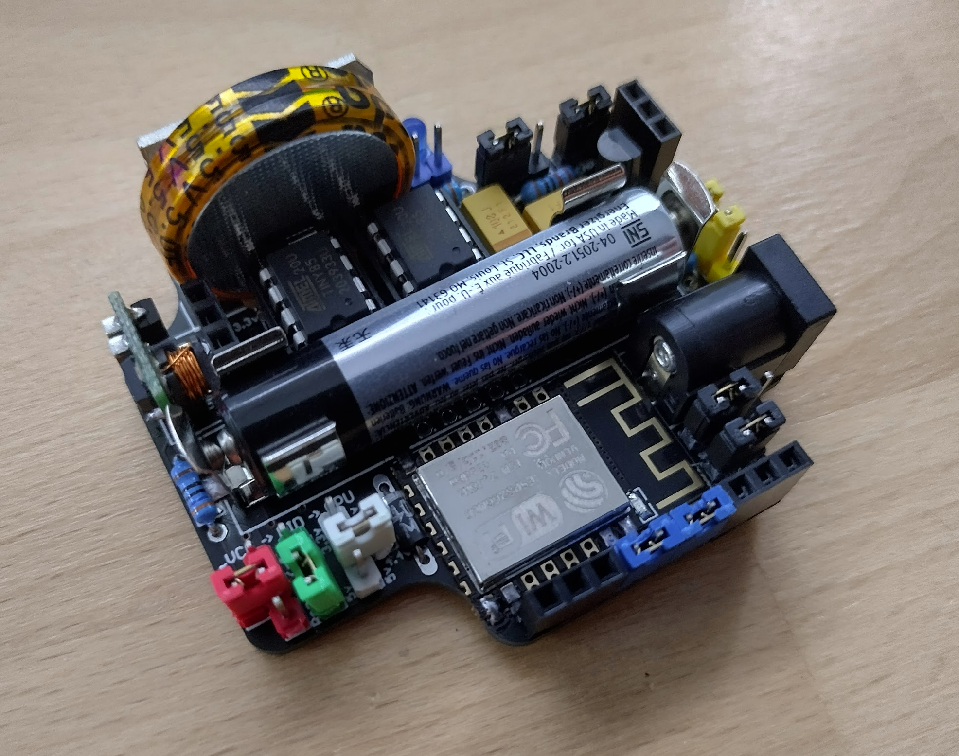
Parts are starting to arrive en masse, and I finally got some of the super capacitors with the right pins. It all fits perfectly! So here’s a peek at the first 100% complete prototype.
This will allow me to test a bit further as I found an issue with the small capacitor on the MID rail the other day. My hope is the big capacitor will smooth it out otherwise I need to find another solution.
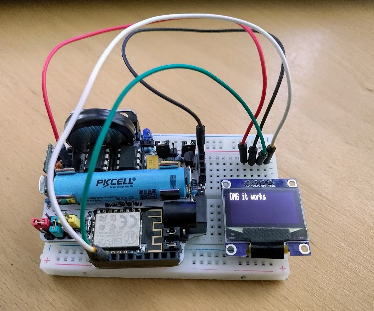
OMG it works
I have been testing this for the last day or so and voltages seem ok, no capacitor fires, etc. I have managed to get a successful OLED hookup to display a message from the net with no trickery so I’m on the right track.
This means the OLED shield I ordered should be ok, and the data pins are connected correctly. The fetching from the net is a bit flaky but the pushing is fine, so next up is the GPS to see if I can get it to post its whereabouts every couple of minutes.
Makeshift system clock & programming
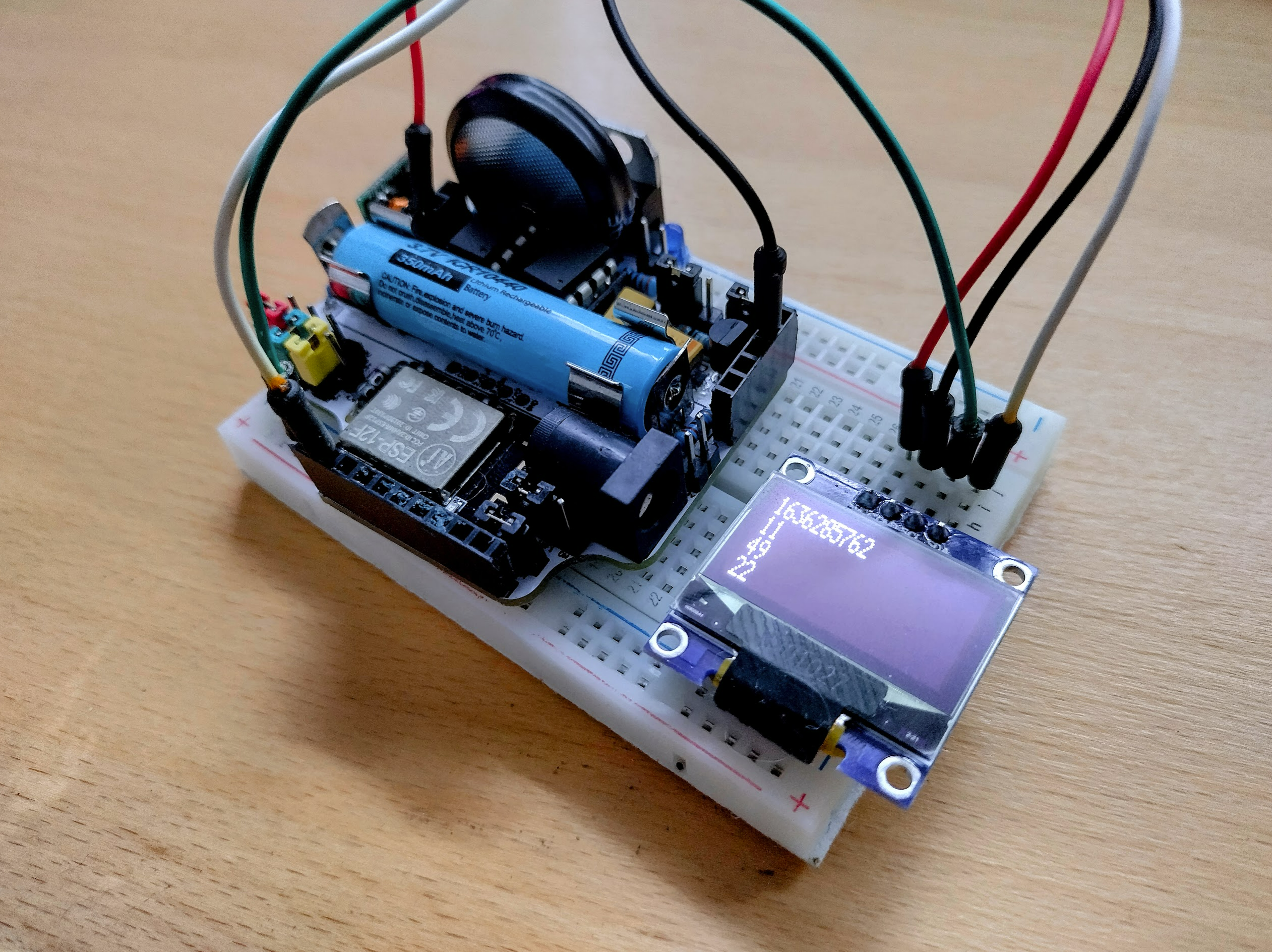
I got a bit sidetracked and wanted to see if I could get a rudamentary clock going on these so that they could synchronise. The answer was to post a timestamp as a header, that the APP chip would detect when it made a web request, and save it back to the bios. In effect setting the system time just like an NTP server. Then once I had the timestamp I could work out the hour, minute, day, etc.
This was quite fiddly and with such a small serial buffer I ended up losing the first few headers of a web request so I had to reorganise those. And the OLED takes up so much precious ram. But eventually success!
That allows me to to all manner of time based trickery. I also purchased some USBTinyISP boards to free up my Arduino Uno, and to come up with a plan to supply these optionally with these boards should someone want to program the ATTiny85 chips themselves. So I have designed a rough veroboard to make use of it…
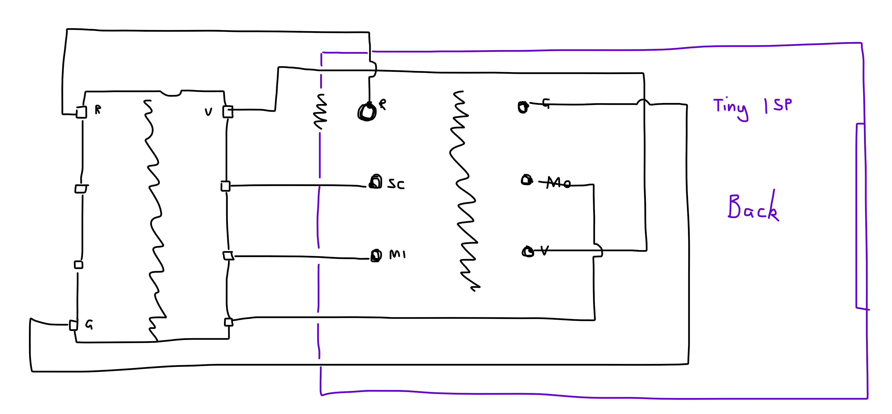
This has been quickly assembled and tried, and it seems to do the trick.
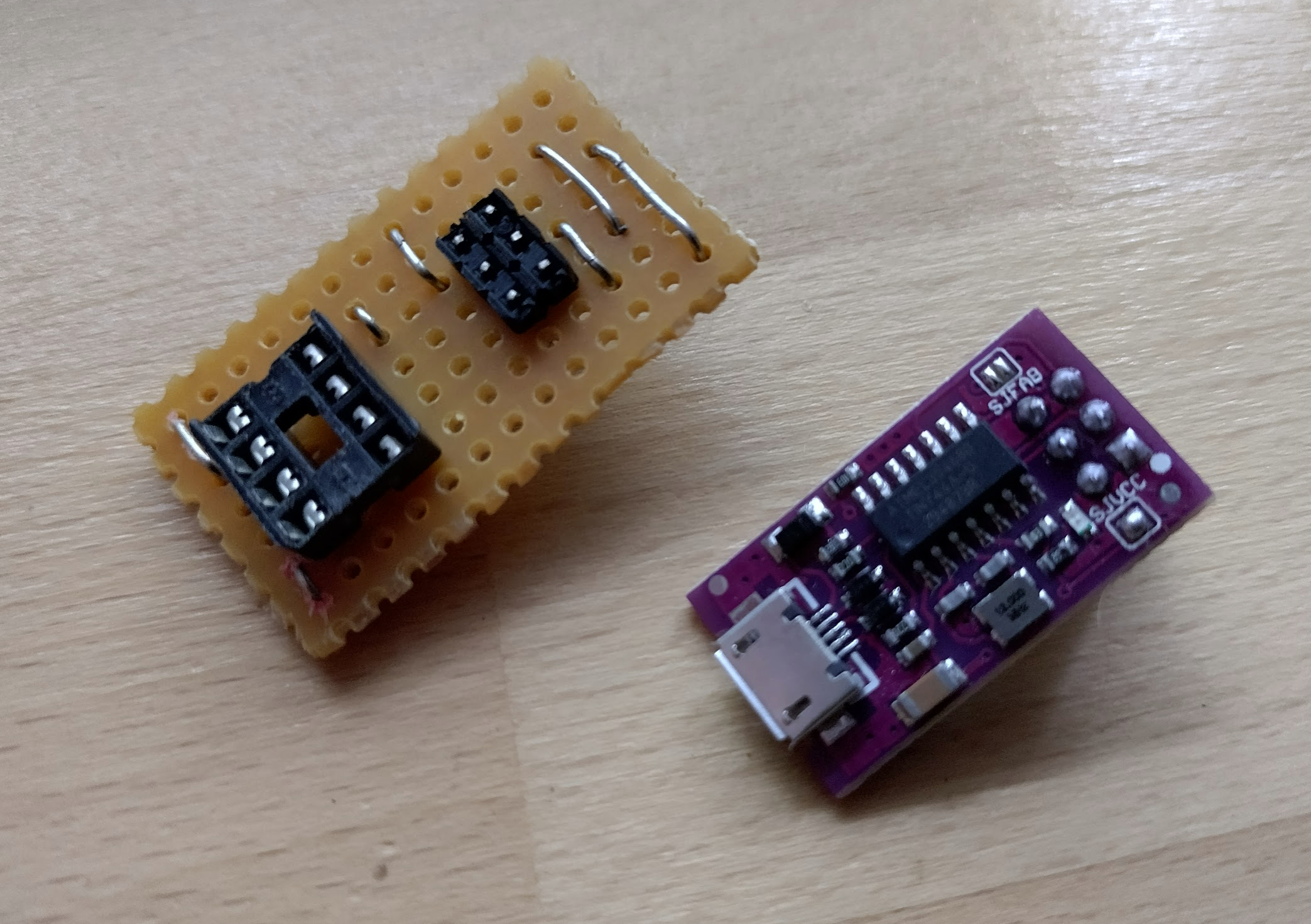
This seems to respond well to the Arduino IDE. So with the next print of boards I’ll make a proper adapter board that can be soldered straight on to this for a more user friendly programmer.
I have heard that V2 of the prototype boards are near so hopefully a second prototype can be constructed soon to prove the DC jack powering of this.
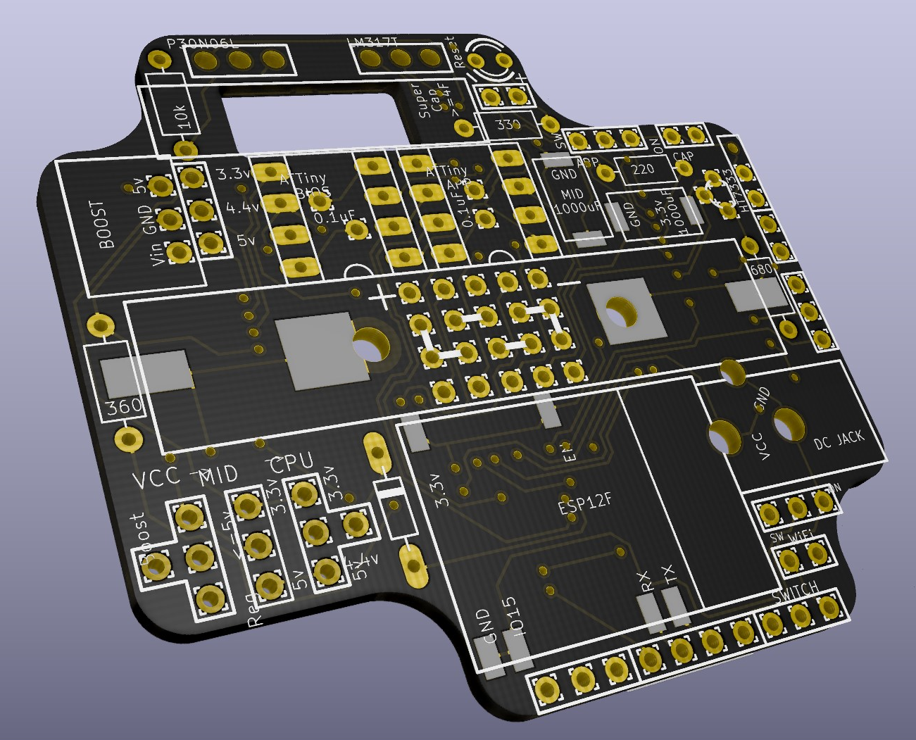
V2 has arrived
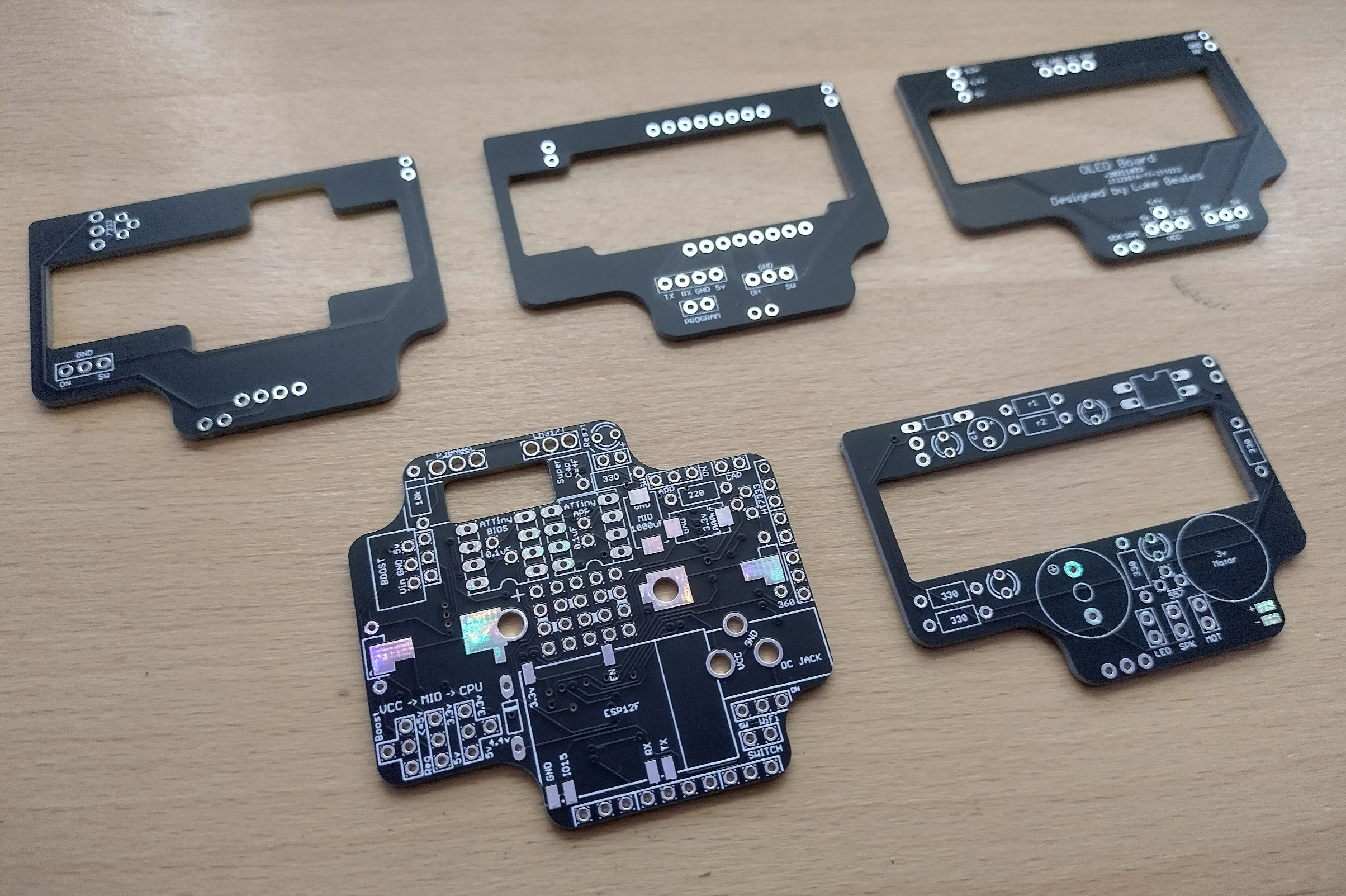
The new boards arrived and the black colour should make it look more cohesive and hide some of the nasty soldering iron burns on the underside. It gives it a more professional appearance. The matte finish was unexpected, but looks great!
Initial placement fixes seem ok, the holes are much better for the DC jack along with the MOSFET and such. The ESP12F pads are slightly adjusted and look better. The mounting holes unfortunately are too small still so there will be another version needed.
I have to wait for further parts which are nearby, so hopefully they will arrive and I can assemble what the end result will look like with the proper colours.
Until then, I am designing a few more boards for ideas, such as a pager / buzzer board, which is commonly used here to alert you when your order is ready.

Hopefully the next update will be a nice photograph of an assembled board.
A few graphics to pass the time
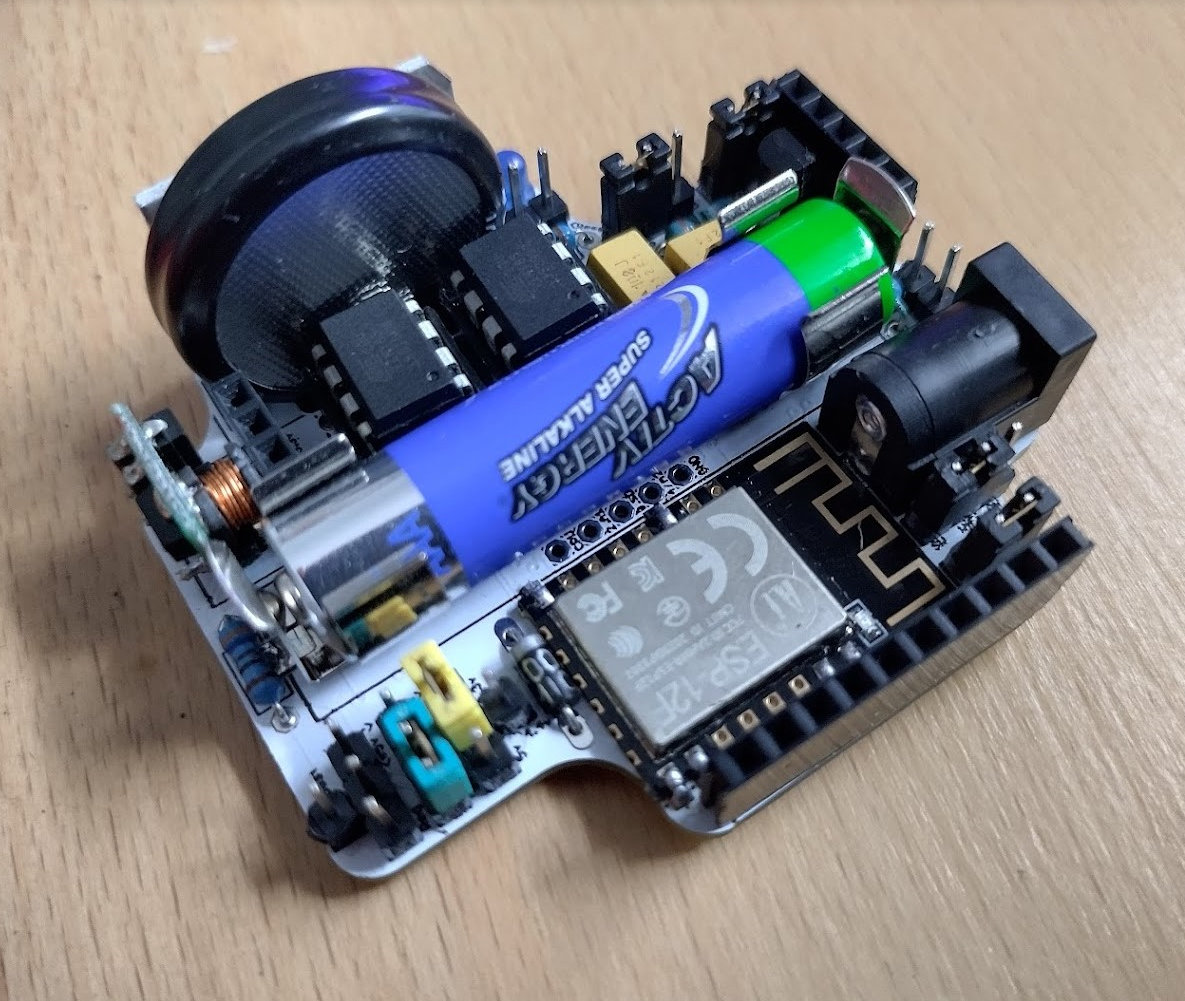
I received a few more new parts this week so it was enough to do a mostly complete assembly and move on to choosing colours of the jumpers that would make the most sense.
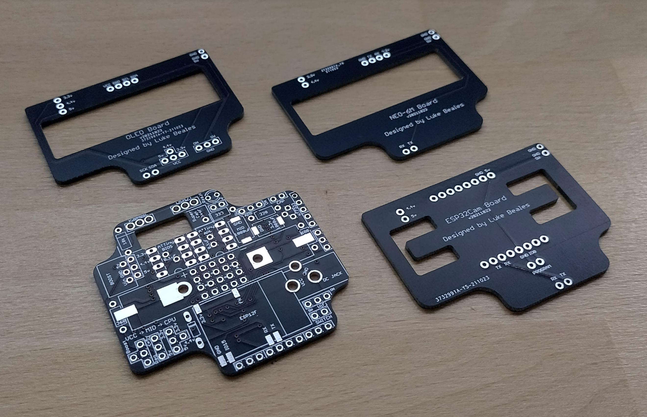
I also put together the shields that sit on top to see what issues they might have as I think a third prototype will be needed, and given the two weeks delay I need to get it sent off soon.

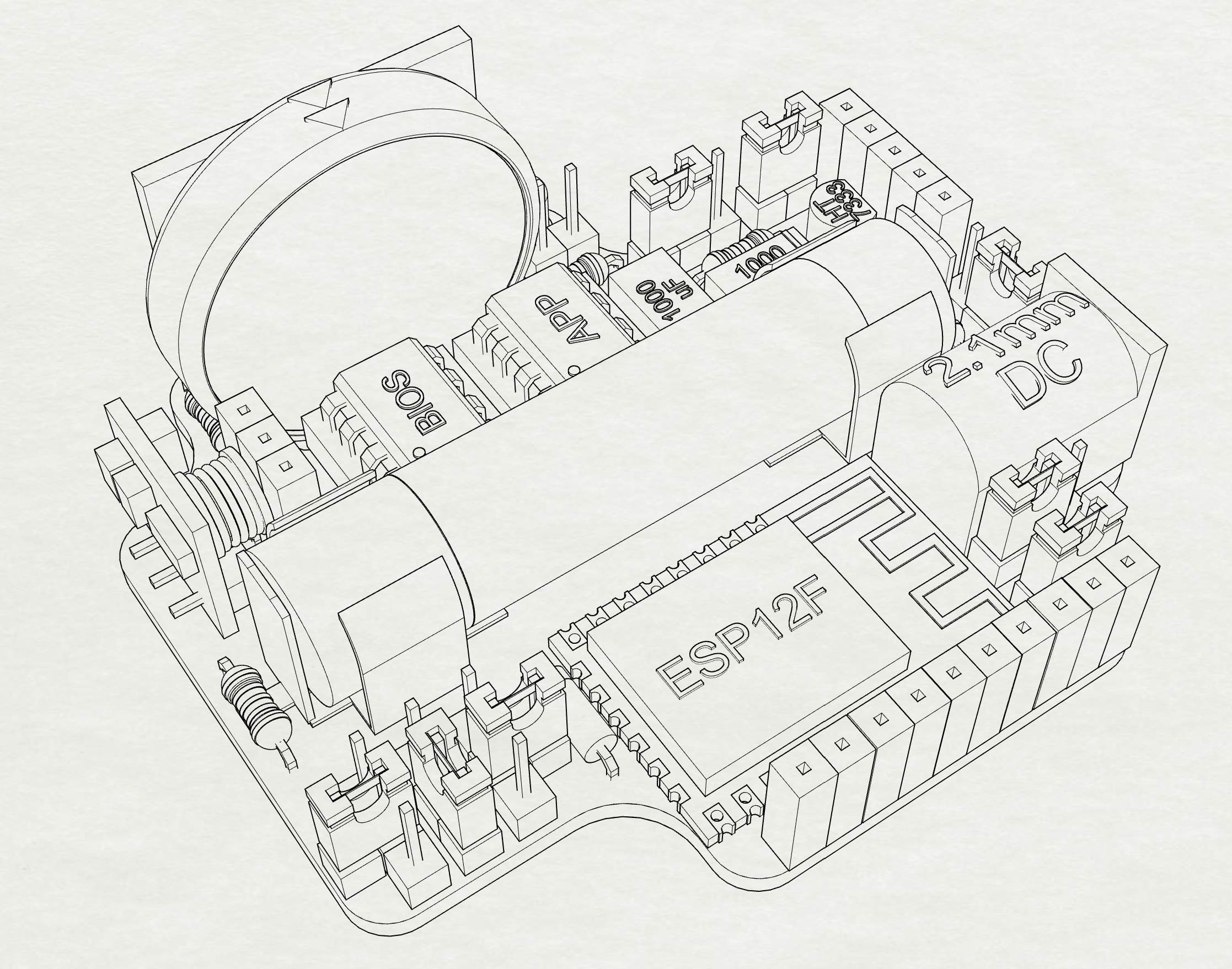
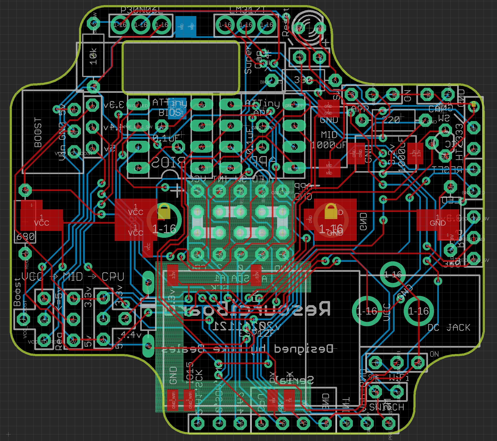
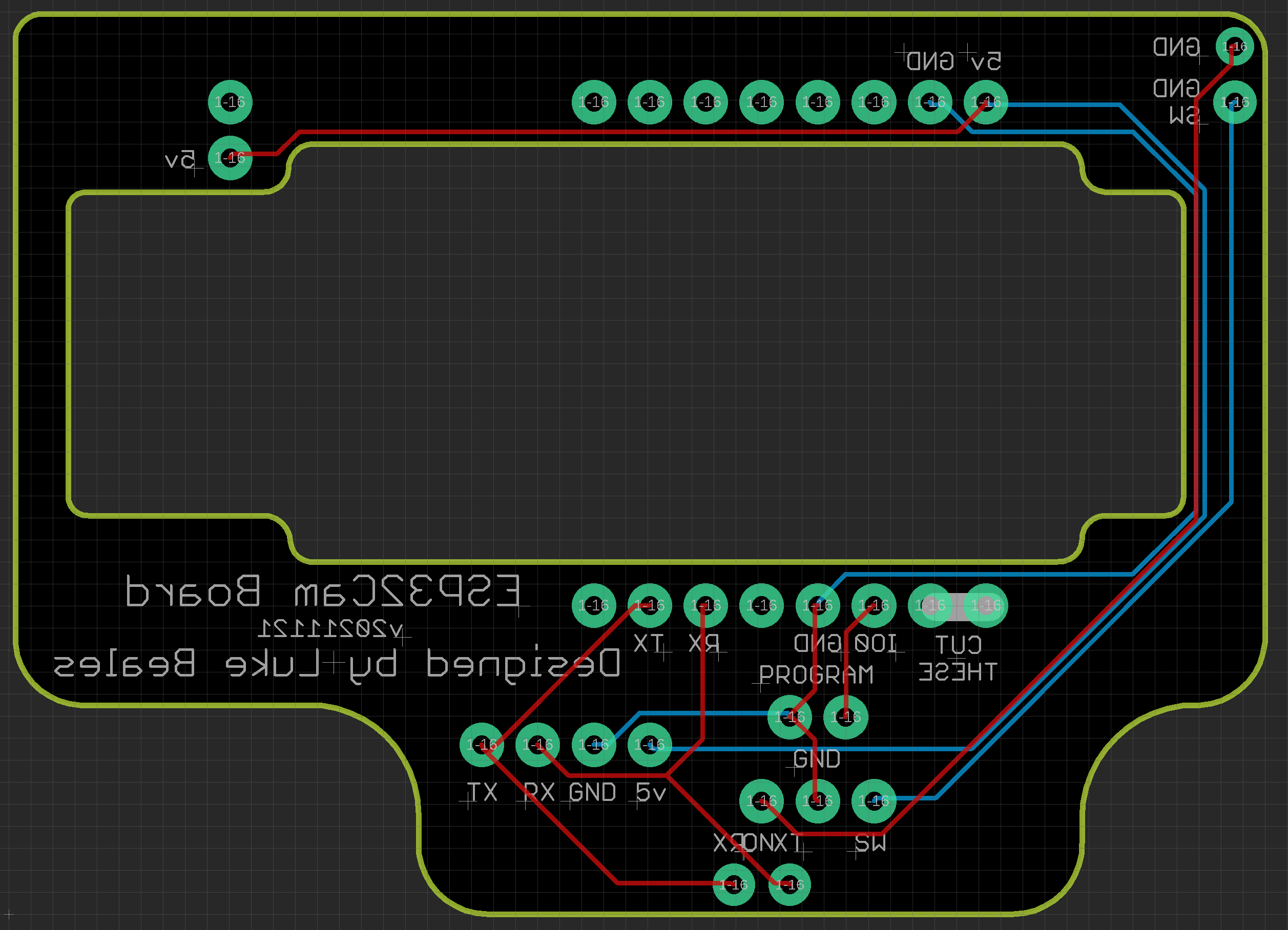
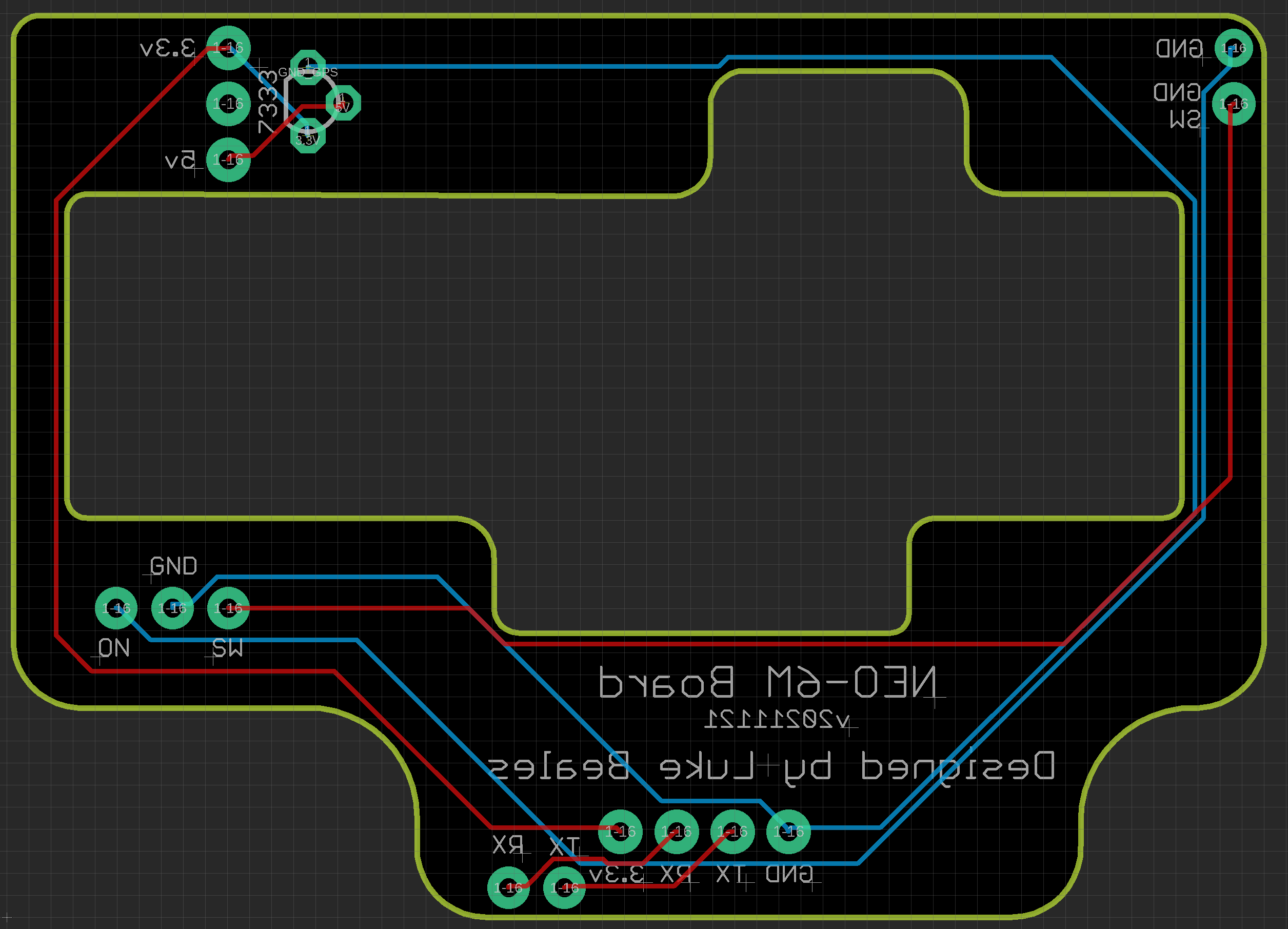
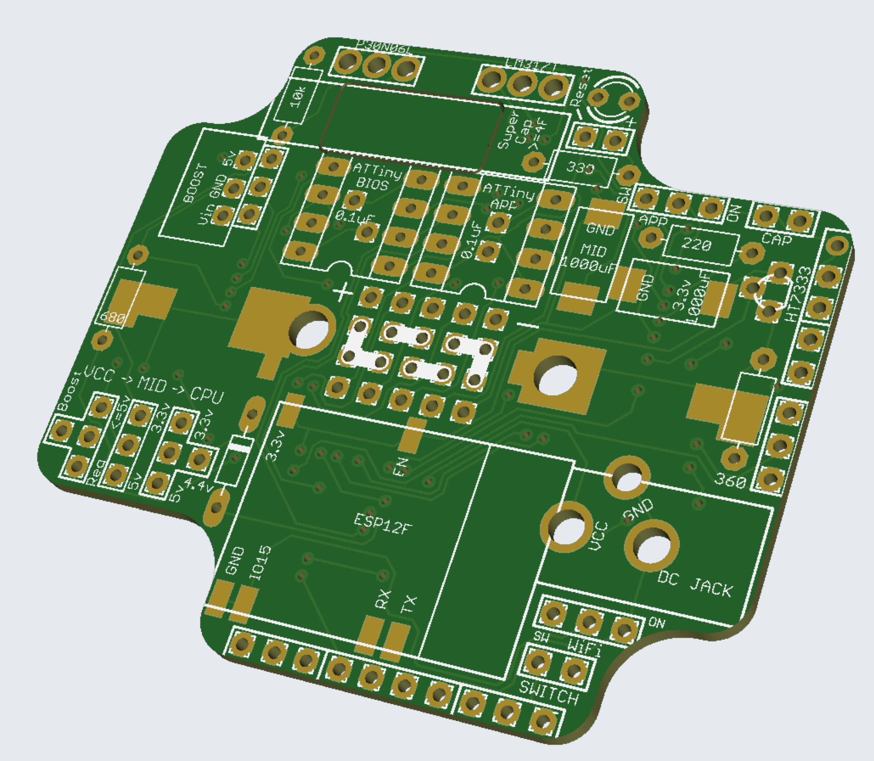
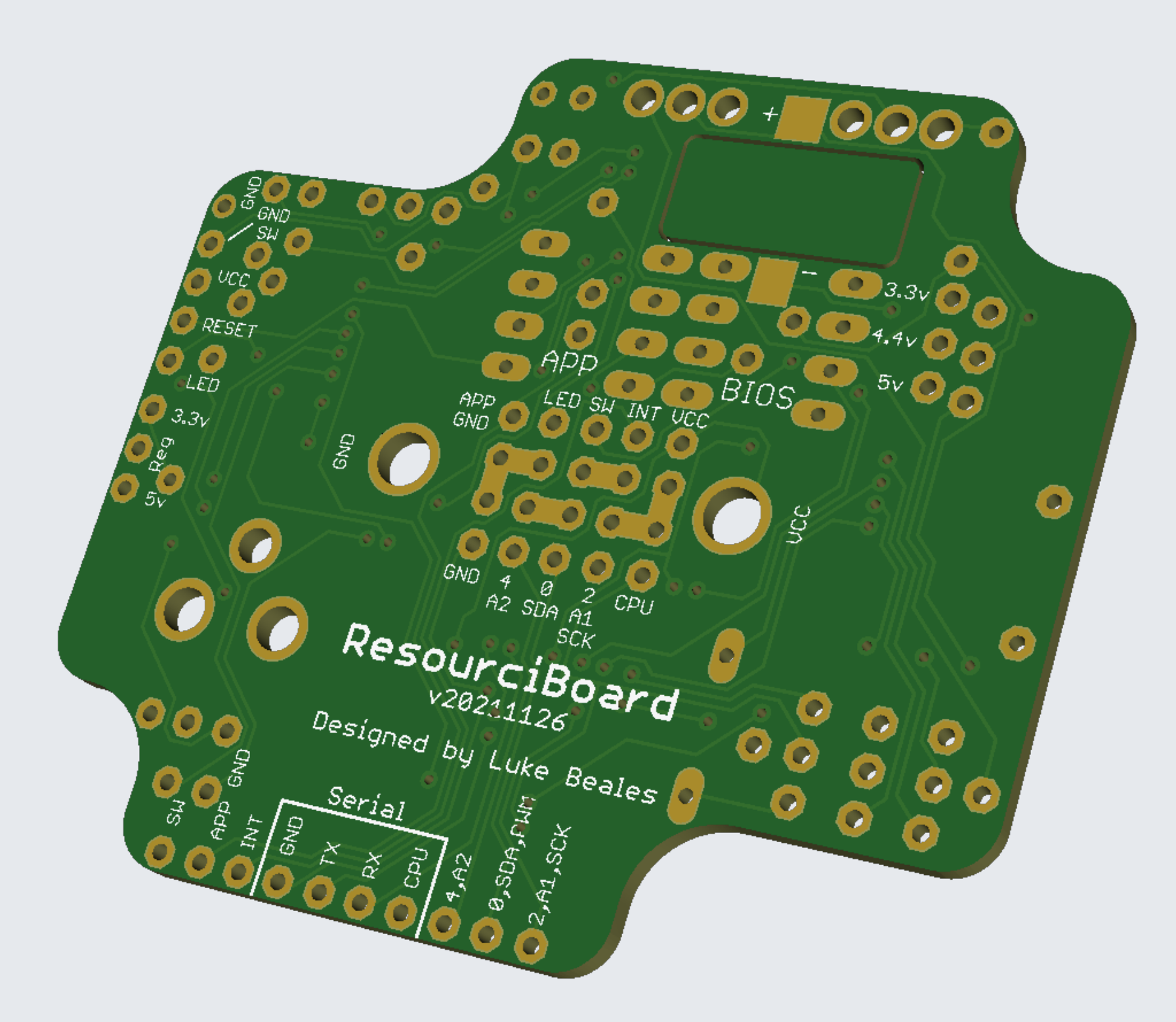
The GPS and ESP32-CAM shields need a few positioning tweaks but they should be good for testing. I am also keeping track of the best order to assemble the ResourciBoards and making a howto document with renders and photos, so here’s a few more renders.

So I have enough to know that some positioning changes were successful for V2, I have yet to power it on as I’m waiting for more parts but I might just go for it to save time. Then I can get V3 on its way while I work on firmware and the App side.
Faulty LM317T linear regulators
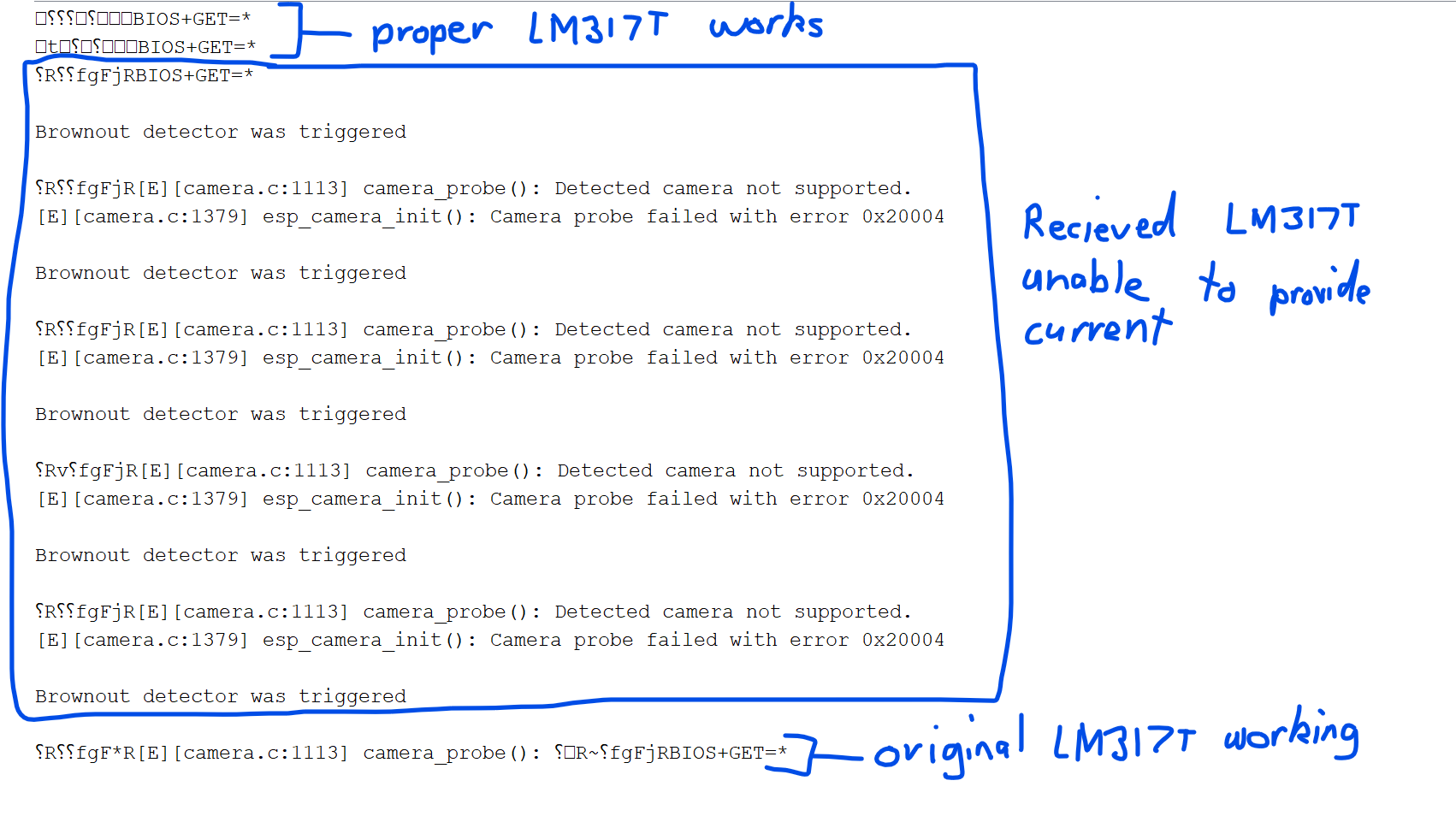
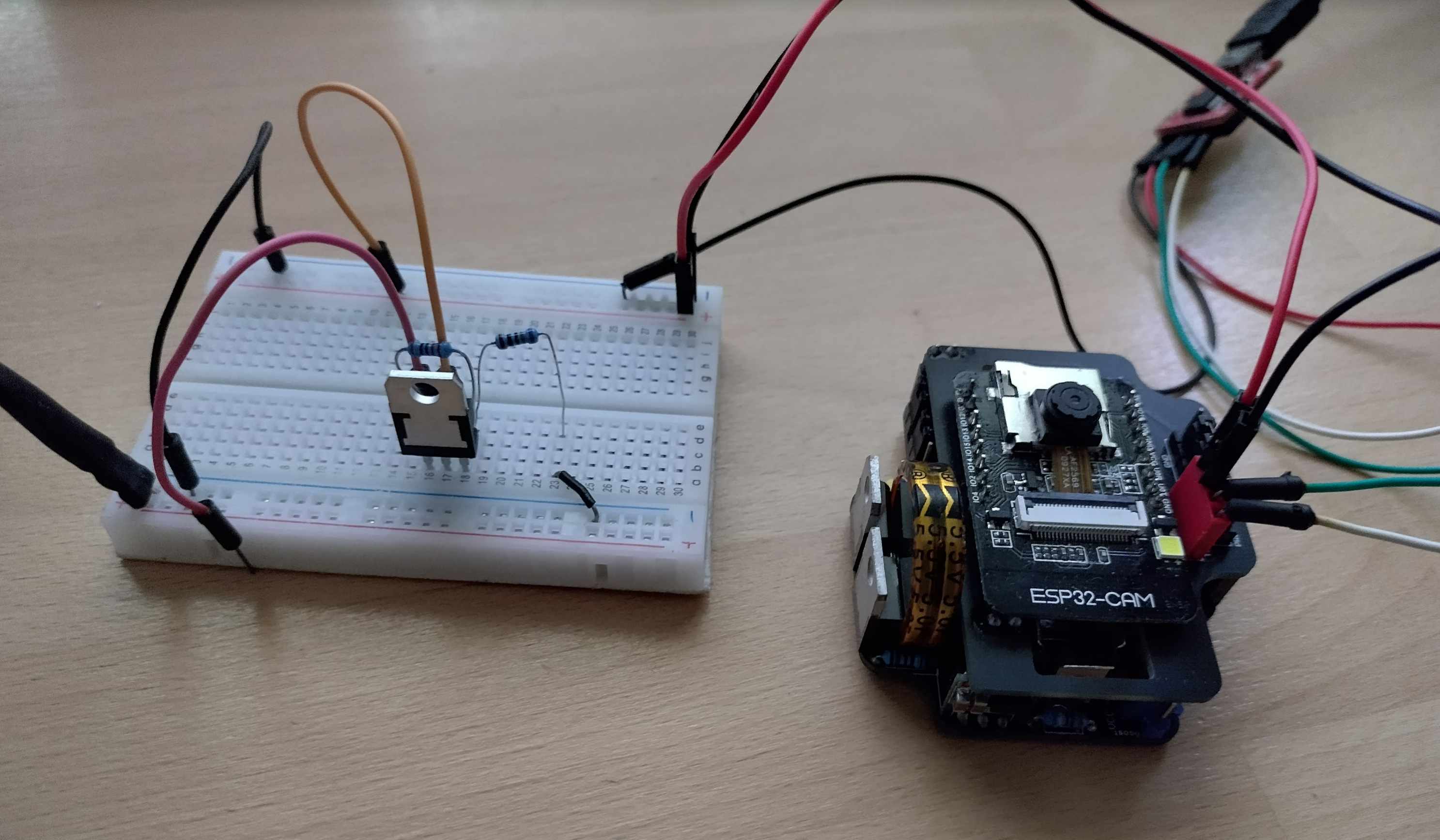
I have been powering it up and trying a few things, it’s looking good with a few labelling changes and no blown capacitors however I discovered an issue where it used to be able to power the ESP32Cam on the original board, but with the new board it can’t. With a lot of trial and error it seems to be the LM317T regulators.
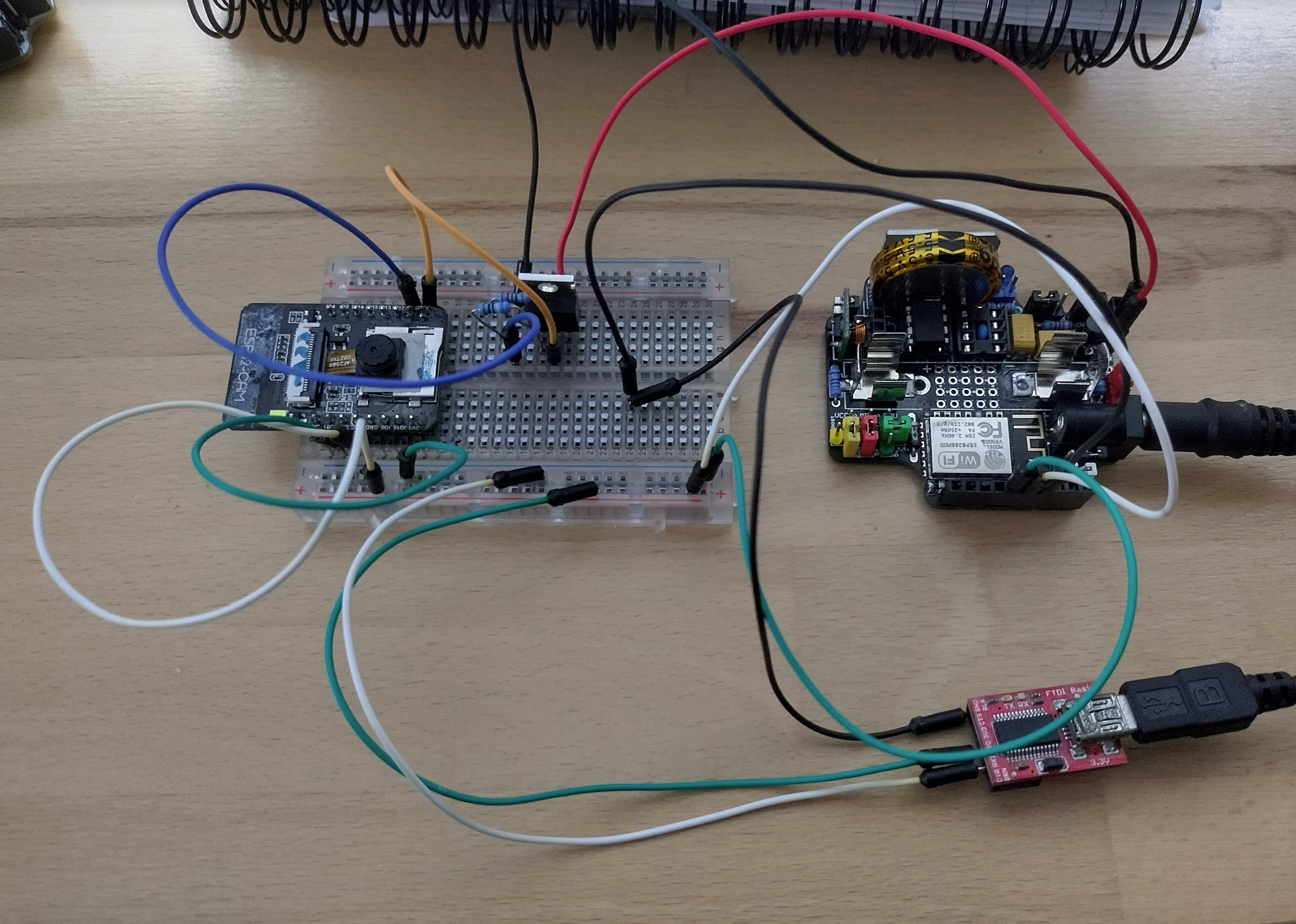
I checked where I got them from and it seems others have found the same issue – the current from them isn’t right. Where it should supply amps, it can only do <200ma. This isn’t enough for the camera.
These are the faulty ones – the comments at the bottom reflect the issue I am seeing: https://www.aliexpress.com/item/10PCS-LM317T-TO220-LM317-TO-220-317-1-2V-37V-1-5A-new-and-original-IC/32842362589.html?spm=a2g0s.12269583.0.0.6e1b40da4cJF99
They’re from a store called “CHIPLIJIAYUE”. Best to avoid it.
These are the ones I was using previously which work much better: https://www.tme.com/au/en/details/lm317-cdi/regulated-voltage-regulators/cdil/lm317/
Hope this saves someone the days of trying to work out what is wrong!
Update: I have ordered some more from a local store and they are testing ok. Here’s the comparison:
Update further: I have ordered more of the LM317t’s and tested them all prior to usage, and discovered a few more to be faulty. There seems to be a few things to look for.
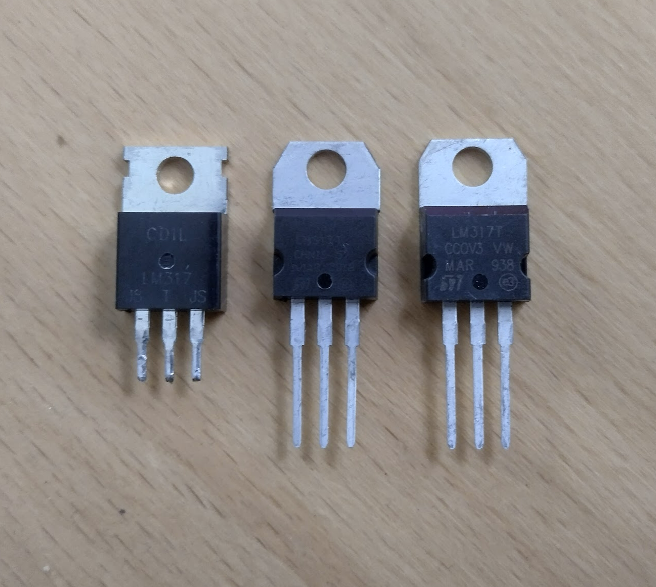
I now have a better idea of what to look for and hopefully this helps others. Here’s the comparison.

The primary differences seem to be quality based. The printing on the good LM317t’s seems to be better, clearer, more aligned. The logo on the bottom left looks nicer. The angles on the metal tab are smaller – I’m unsure which angle is more to spec. And a big difference I noticed is the thickness of the metal including the pins.
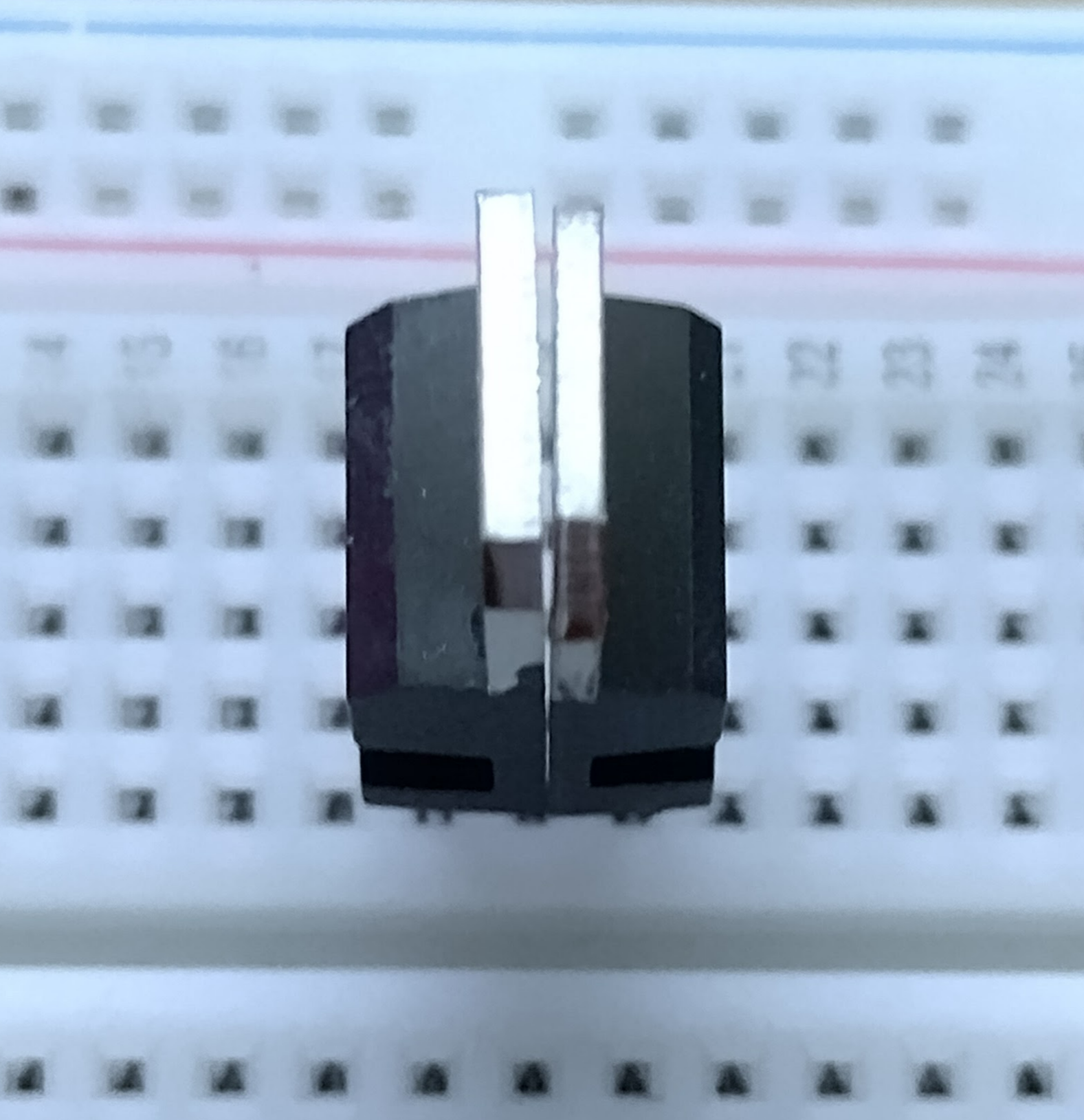
The faulty ones have far thinner metal and the pins can be pushed in to a breadboard with ease, whereas the good LM317t requires decent force to push in to a breadboard. These tips don’t help when ordering of course, but it might help before solding something together.
Refinements
I have spent the day cleaning up some of the issues I have discovered as I continue testing. Most of the issues are cosmetic or physical fitment.
I have also received most of the parts I need for the new pager board so I have been busy designing so that it can be sent along with the other boards for a new print.
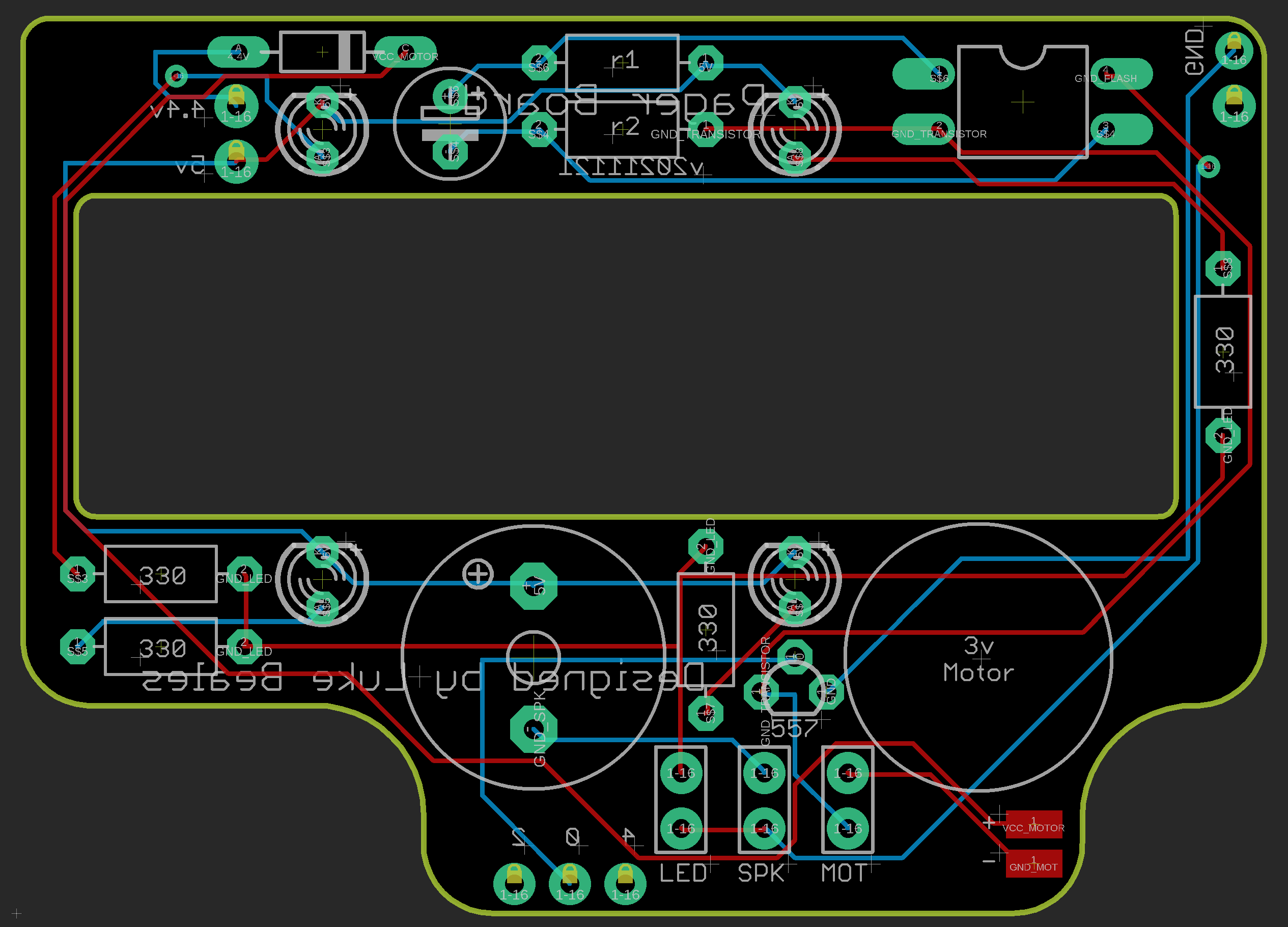
These are now looking pretty good. I need to wait for the new LM317t’s to test, and the buzzer component to see if the holes are in the right spot. If those two things work out then it’ll be ready to send off.
I also received a second batch of “Yellow” pin jumpers, read about the debacle here.
Update: Buzzers arrived and look good, and LM317T’s test ok. Also got the ESP32Cam to work correctly so all the above boards have been sent off to manufacture! I can already see one issue but it’ll do for now.
Hopefully this will now result in a working solo board, pager board, ESP32cam board, OLED board, and GPS board!
Power issues, ESP12 WiFi strength
While doing some testing with the OLED board I noticed odd behaviour where it would get stuck, not just the APP chip but also the BIOS which should be independent of it. It would keep the switched line high.
The issue appeared to be if the device was a little distance from the WiFi access point. Debugging this I discovered it wasn’t getting an IP address quick enough (within 5 seconds). There isn’t much memory in the ATTiny85 so I was just moving on IP or not, and getting it to fire off commands to connect to the website and do its thing. With an IP this works perfectly. Without an IP it causes a massive power blip which confuses everything and puts it in a sort of nirvana between On and Reset. If I remove the OLED while it’s in this state, it generally fixes itself.
So to fix this I am trying to get the data back from the ESP12F which I have tried everything with no success. I have discovered however that loops and millis() seem to use a lot of power and cause the APP chip to eternally reset if the ESP12F is still hunting for an IP. Using the lower power ATTiny85v chips didn’t help.
I also suspect the 3.3v regulator and the boost boards (and possibly the capacitors) have been damaged slightly which probably isn’t helping find the solution.
Given the new boards are only a week away I am going to wait until those arrive so I can make a clean one. Assuming I haven’t broken anything on the mainboard design, and the camera measurements are ok, it should at least let me have 4 cameras going which was the original plan behind this.
Fingers crossed!
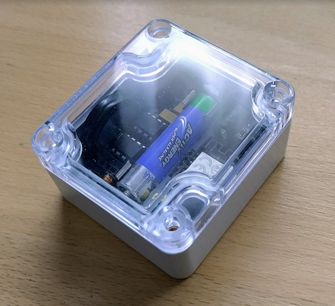
V3 is here!
The latest round has finally arrived just in time for christmas testing! I thought they wouldn’t for a minute there, but the 2 to 2.5 week timeframe is staying true.
It’s coming together, and all the cutouts and refinements so far look great. No obvious issues, only cosmetic such as silkscreen labels that I forgot to move. So there will be a V4.

It’s only been minor adjustments going through which shows the 3d modelling has helped dramatically in the beginning. The v4 will hopefully just be silkscreen updates.
Time to get soldering, see how this turns out in part 5.